OK, your vehicle expects a 450-100 ohm float (empty-full), but your fuel cell has 0-100 ohm output (empty-full). You got the fuel cell already, gotta live with it. Gotcha.
For reference, Polaris PRO uses 12 V battery.
This will require an active circuit that measures the resistance on the float, maps it to the output resistance range, and then emulates this resistance.
There are many ways of doing it.
The control unit reading the float will maintain voltage on both of the float's terminals somewhere between 0 and 12 V, and our "resistor emulator" needs to accommodate that.
One approach would involve a chopper that "chops up" a 100 ohm resistor's conductance to emulate higher values.
The system diagram of such a circuit is as follows:
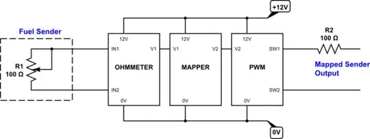
The 0-to-100 ohm fuel sender is connected to an ohmmeter circuit, which converts the resistance to a voltage V1. This voltage is then mapped to a voltage V2, which corresponds to a PWM duty cycle needed to emulate the 450-to-100 sender. The PWM's output appears like a quick switch that turns on-and-off, with the on-to-off ratio such that it makes the 100 ohm resistor R2 appear to be anywhere between 100 and 450 ohm.
With PWM duty cycle at 100%, the resistor is continuously connected to mapped output and appears just like itself: a 100 ohm resistor. At duty cycle 50%, the resistor is unplugged half the time: it looks like it has half the conductance, or twice the resistance - it "becomes" a 200 ohm resistor. And so on. At 22.2% duty cycle, the resistor is unplugged enough that it has 2/9ths of the conductance, or 4.5x the resistance - it "becomes" a 450 ohm resistor.
So, the mapping we need is 0 ohm on the input (empty) to 22.2% duty cycle on the output (450 ohm - empty), and 100 ohm on the input (full) to 100% duty cycle on the output (100 ohm - full).
The chopper approach is cumbersome to execute with parts that can be modeled in CircuitLab, as my goal was for the circuit to be easy to simulate directly on EE stack exchange.
After trying it out and deciding it wasn't a good example, I've instead adopted a continuous-time approach that is much simpler. This is the answer that details that circuit.
The circuit as presented there is only a proof of concept, because automotive environment is generally harsh, so it'd need various additional components to stabilize the supply voltage, protect from overloads, etc.
