I'm having ignition problems with my car (1985 Suzuki Samurai). Sometimes the engine will die randomly while driving, and often when warm it will have problem starting.
I bought a new ignition coil, but it didn't work correctly. The new one have all the symptoms of a bad coil (rough idling, poor performance, engine almost dying). So I put the old one back (shown at right in photo below). And now I don't know if the new is defective, or it's because I hooked it up wrong, or maybe it's not getting enough power?
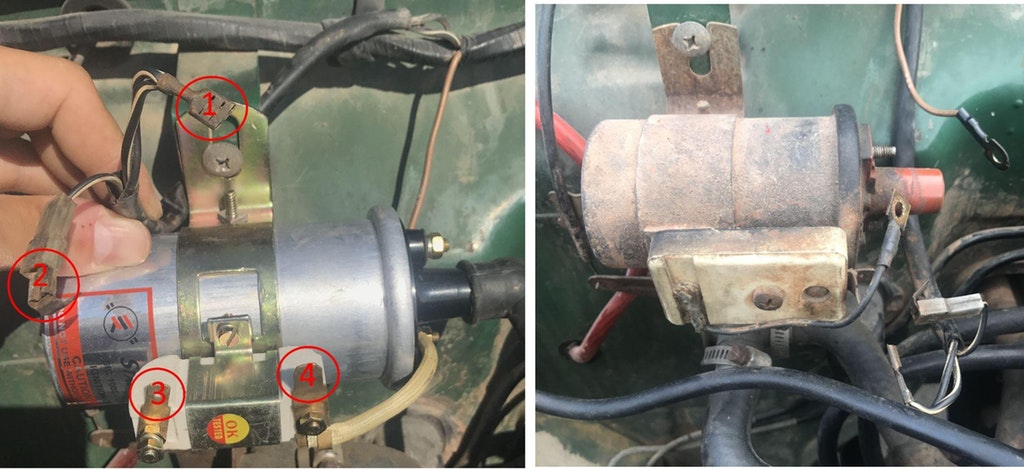
I don't understand quite how the wiring works here, could someone explain? (see photo below)
Why are there 2 wires? (1 and 2). Only number one has 12V when ignition is on? Which should be connected at which point (3 and 4)? On the old one, the two connection points are soldered together...
I have a multimeter - what should the correct voltage be at the vaious points when hooked up?