8

Am planning to install a carputer (Raspberry Pi) in a 2005 Ford Mondeo, replacing the car stereo. The Quadlock connector to the stereo apparently includes CAN bus, so I am thinking I will get a USB OBD-II adapter and just solder the relevant pins.

enter image description here

6, 14, 16 are CAN bus and battery plus.

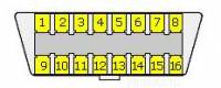
On 4 it says "chassis ground" and on 5 "signal ground". I think I understand linguistically what that means, but am not sure why you need both. (Is that even the CAN bus signal?)

Since I only have one "ground" on the Quadlock, which I assume is battery minus, connected to the chassis, what should I do?

Both 4 & 5 to ground or ignore OBD-II pin 5?

Clarification: I am not going to use the car OBD-II port, only the Quadlock connector.

Edit: what I am really wondering is why the OBD-II standard has both chassis and signal ground. I find it hard to believe they are just the same.

More clarification: the car has an OBD-II port under the steering wheel. I am not talking about that one. The one I mean is the "in" connector to an adapter for interpreting the bus computationally. The adapter is connected to the computer via USB. I am going to remove that connector and connect the pins I need to the car via the Quadlock connector.

Tomas By
  • 215
  • 1
  • 2
  • 7

2 Answers2

9

You are over thinking things, just connect your devices (OBD & Pi) to a good chassis ground:

The difference between chassis and signal ground is:

  • Chassis Ground Pin 4: Is exactly that, connected directly to the chassis or battery negative terminal.
  • Signal Ground Pin 5: Is designed to provide a 'clean' ground isolated from any noise from devices such as radios, alternators and poorly designed switching regulators.

Usually signal ground comes from the Engine ECU, diagnostic gateway or nearest ecu/module, signal ground always ends up to ground through either a cleverly designed ground plain in the ECU/Module or through a number of 0Ω resistors or connected at a point far away from any noise.

So Signal ground and chassis ground always end up connected to the battery negative terminal but the signal ground is just isolated from any noise.

Only use signal ground as a reference when monitoring data, for sensors or diagnostics. This is because you cannot guarantee it is designed to carry significant current.

Now in the real world and especially on cars with little electronics such as your Mondeo you usually find that signal and chassis ground are just connected directly together somewhere in the loom.

CAN bus data is resilient enough to use chassis ground as a reference. You have no problem connecting everything to a good chassis ground.

While 99% of the time you will be ok connecting signal and chassis ground together, it's really not good practice as any noise on the chassis ground could now disturb any thing sensitive such as a diagnostic computer connected to signal ground.

Now when it comes to connecting your USB to OBD device connect pins 4&5 on the device to chassis ground. Don't connect pins 4&5 together on the actual vehicles OBD port for the above reasons. As for the lives you also don't have to worry about getting them from the OBD port, just connect to the required permanent and ignition lives on the quad lock.

Newbie Noob
  • 2,792
  • 11
  • 23
3

As Ben stated in the comments, they are both usually grounded to the same point on the chassis. My suggestion to you is to just ground it to the chassis and ignore the #4 & #5 pins altogether. The more you mess with the wiring directly, the more issues you're going to have. Chassis ground is almost always a good bet, especially when all you are looking for is a point for a grounding source.

Pᴀᴜʟsᴛᴇʀ2
  • 165,084
  • 32
  • 259
  • 508