5

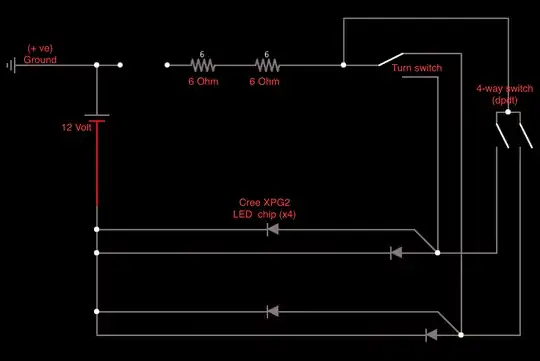
I have a 1976 Triumph Bonneville and recently replaced the garbage LED chips inside the eBay signal lights with brighter Cree LED chips. I bench tested the circuit shown below with a 12v bench supply and everything worked perfectly. I also tested it with the motorcycle battery with the same success. However, once I began installing the system and testing it on the motorbike as I went along, I've been burning out LED's (they only glow dimly when fried). I want to know what I am doing to be frying these things left right and center!

I will mention that the bike is positive ground. This means the LED lighting circuit cannot ground to the frame and must have it's own closed circuit directly to the battery. Occasionally when wiring I'll have the battery connected and one of these negative return wired will spark off the bike (potential culprit?). What do you guys think is killing the lights?

I've already come up with some potential solutions:

  1. Adding protection diodes in the reverse direction parallel to the led's (prevent reverse current)

  2. Make absolutely sure the wire attaching to the chips are insulated from the metal lamp housing.

  3. Add a tiny fuse to each leg of the circuit.

Here's the wiring diagram:signal lighting

Thank so much everyone!

Paul

dlu
  • 14,506
  • 8
  • 52
  • 85

4 Answers4

1

Did you factor in the resistance supplied by the fuse? Fuses will add resistance (of some level or another) and smaller fuses (smaller conductors) will supply more resistance.

But, as noted in the comments, check the voltages at various points (before and after each element).

Also, where is the fuse on your diagram?

UPDATES

Occasionally when wiring I'll have the battery connected and one of these negative return wired will spark off the bike (potential culprit?).

Yes. LEDs are generally very sensitive to voltage/amperage flux and shorting while doing wiring could definitely do that.

I will mention that the bike is positive ground. This means the LED lighting circuit cannot ground to the frame and must have it's own closed circuit directly to the battery.

As a slightly less important point, why can't you draw the positive (+) from the frame and the negative (-) from the power circuits?

In addition, as dlu mentioned, you will be pulling more than 12VDC if you tap the battery directly, or are otherwise not going through a voltage regulator (VR)... So if you are doing a straight battery pull, you need a VR.

kyle_engineer
  • 3,289
  • 12
  • 23
1

There are two things here that sound like possible culprits:

  1. When the bike is running the voltage seen by the LEDs will be the output of the alternator or generator, which will be around 14.2 V, depending on the LED you're using that might be enough to cause problems.

  2. The sparks. They are not a good thing. They imply that there was a sudden rush of current. Off hand I wouldn't expect much current to be drawn by the LEDs in their correct configuration, so I'm not sure if you would see a spark in normal circumstances (if the circuit had enough resistance to limit the current to the LED's spec).

It sounds like what you are trying to do it to upgrade the LEDs in an already working circuit. In that case it would be good to look at what you had and what you're doing with an eye to what is different. It would be good to understand why any changes were made – or at the very least to know what the changes are and be able to ask about them.

I'm curious about the positive ground. I can't see any theoretical problem with running a separate ground for the turn signals back to the battery, but it seems like it adds a complication and may lead to confusion down the road. Couldn't use modify the circuit to accommodate the positive return and do your switching on the negative side? It seems like that would avoid possible problems with the return path and the confusion of having two different wiring conventions on the bike.

Looking at the data sheet for the Cree XPG2 I see that reverse voltage spec is only 5 V. That makes me think that it would be pretty easy to fry one of these if you hook it up backwards even for a second. So be very careful of that, both as you work and in your circuit design.

dlu
  • 14,506
  • 8
  • 52
  • 85
0

The calculations I have done show that you will only be driving 0.5 amp through the LEDs when the supply is at 14 volts, so you should be ok, since they can take 1.5 amps.

Touching the negative wire against the chassis will be shorting the battery, and so bypassing the LEDs, so they shouldn't be damaged.

The only thing I can think of is that you haven't got a sufficient heat sink. These LEDs rely on the surface that they are soldered to to keep them cool. Have they got sufficient cooling? If not they will quickly get hot and become damaged.

Possibly on the bench running off a battery at 12volts, the lower current will stop them getting hot enough to damage them.

HandyHowie
  • 25,681
  • 3
  • 40
  • 76
0

Could the diodes in the rectifier be leaking voltage in the reverse direction? I could see that causing your problem but the battery wouldn't charge very well. Do you have the original Lucas rectifier?

Eric
  • 584
  • 1
  • 3
  • 10