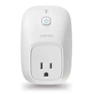
I have a Wemo Smart Switch similar to the one in the picture below.
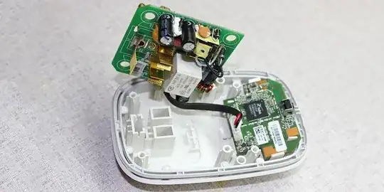
Using Wemo app from an iPhone the switch can be controlled. I am interested in learning electrical signal behavior of the white wire (as shown in the picture below) which I believe is the one responsible for controlling the Wemo Smart Switch.
I have been looking at Belkin WeMo Teardown. Based on the Belkin WeMo Teardown looks like there is Power PCB and Logic PCB. Depending on the switch there appears to be a 3 wire or 5 wire option.
Looking at OpenWrt Wiki Belkin F7C027 it looks like the signals are
- White (GPIO13) - AC Relay control
- Black - GND
- Red - 5V
- 3.3V
- GPIO14 - 0V off (default) 3.3V on
As state above does anyone know the electrical signal behavior of the white wire? Is the signal a simple High/Low (on/off), pulse (toggle) or something other like a pulse train (data communication)?

