TL;DR When trying to use some pins of my ESP32 to read analog signals, it turns out those pins have a non-zero voltage, messing up the measurements. Why?
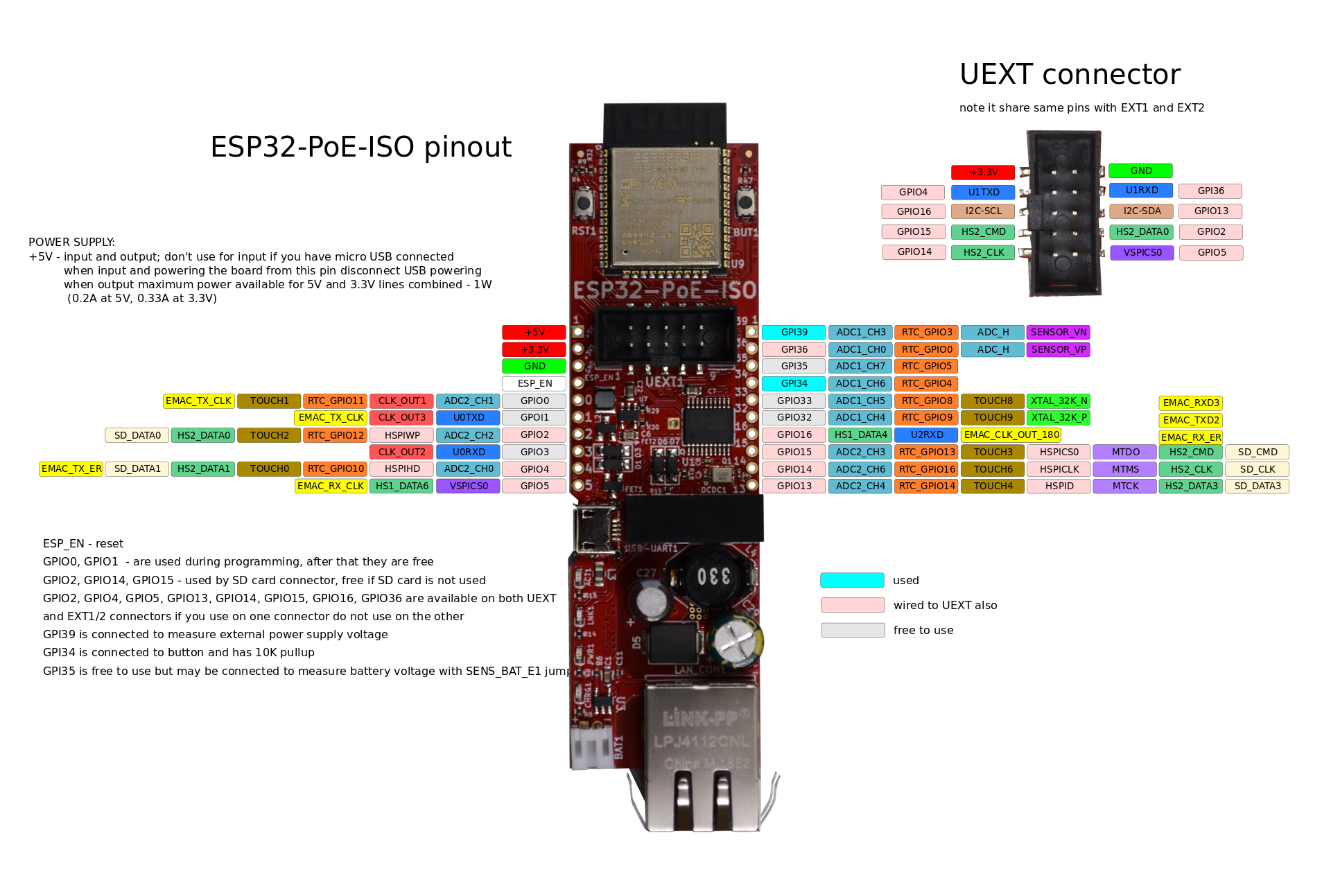
I got myself an Olimex ESP32-POE-ISO (see specs) to run the irrigation of my garden. I am attaching some hunter valves on GPIO0-5 and the plan was to hook up 3 moisture/temperature sensors (Truebner SMT50) to the pins on the other side of the module (see pinout).
However, I ended up pulling my hair out. On some pins (e.g. GPIO14/ADC2_CH6, GPIO32/ADC1_CH4, GPIO33/ADC1_CH5, GPI35/ADC1_CH7) I get proper readings. I've tried both features (moisture and temperature) of each of the 3 sensors on those pins and the values I get look reasonable. So I am ruling out defective sensors.
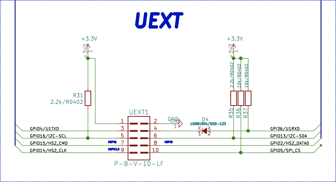
I have also tried GPIO13/ADC2_CH4, GPIO15/ADC2_CH3, GPI36/ADC1_CH0, GPIO0/ADC2_CH1 and GPIO2/ADC2_CH2, but I always get numbers that are way to high (raw values at 12bit between 2400-3400, corresponding to voltage 1.9V - 2.7V). And in fact, after disconnecting the sensor and measuring with a multimeter I could find that those pins actualy do have such a voltage (measured against the GND pin) while the "good" pins do not have that.
The initialization code looks like this (channel.channel.adc1_id and ...adc2_id contains values like ADC1_CHANNEL_0, ...):
void SensorService::init() {
    ESP_LOGI(TAG, "Initializing sensor service");

    adc1_config_width(ADC_WIDTH_BIT_12);
    sensorToChannel = getChannelMapping();
    for( const auto& [ idx, channel ] : sensorToChannel) {
        switch (channel.unit) {
            case ADC_UNIT_1:
                adc1_config_channel_atten(channel.channel.adc1_id, ADC_ATTEN_11db);
                break;
            case ADC_UNIT_2:
                adc2_config_channel_atten(channel.channel.adc2_id, ADC_ATTEN_11db);
                break;
            default:
                ESP_LOGW(TAG, "Invalid ADC unit requested");
                break;
        };
    }
}
The reading of raw values like this:
std::optional<unsigned int> SensorService::getRawValue(unsigned int sensorIdx) {
    ESP_LOGV(TAG, "Getting raw value for sensor %d", sensorIdx);

    if (!this->isValidSensorIdx(sensorIdx)) {
        ESP_LOGW(TAG, "Requested non-existing sensor");
        return std::nullopt;
    }

    TargetChannel target = sensorToChannel.at(sensorIdx);
    switch (target.unit) {
        case ADC_UNIT_1:
            return std::make_optional(adc1_get_raw(target.channel.adc1_id));
        case ADC_UNIT_2:
            int value;
            adc2_get_raw(target.channel.adc2_id, ADC_WIDTH_BIT_12, &value);
            return std::make_optional(value);
        default:
            ESP_LOGW(TAG, "Invalid ADC unit requested");
            return std::nullopt;
    }
}
And this works perfectly fine for some pins but not for others.
I also tried a few things I could find in the docs to set the pin explicitly to INPUT and low. But it didn't change anything.
    for (auto const& [ sensorIdx, pin ] : sensorPins) {
        gpio_pad_select_gpio(pin);
        gpio_set_direction(pin, GPIO_MODE_INPUT);
        gpio_set_level(pin, 0);
    }
I am powering and connecting to the board via Ethernet/POE. I am not (knowingly) activating WIFI, RTC, hall sensor anywhere in the code. Not using SD card nor the flash memory for data storage. The values will only be polled via HTTP/Ethernet.
So, my actual question here is, why do some pins (e.g. GPI36, explicitly documented as input-only pin) have non-zero voltage while others haven't? What am I missing?