24

I want to make a home automation system, and I need some computer-controllable switches. The reason I can't use relays is that I also need the switches to be switchable manually and not programmatically (because I don't want the light to get stuck in whatever status it's in at the moment when the program controlling the switches is going to crash). However, I am not sure what is the canonical way to make something like that.

The options I've thought of so far:

  • A regular switch with a servo duct-taped onto the back
  • A switch connected to a microcontroller (like an Arduino) that inverts the signal every time the switch is toggled
  • A switch that sends messages to the microcontroller connected to the lamp telling it to inverse the state of the output
Bence Kaulics
  • 7,843
  • 8
  • 42
  • 90
Danya02
  • 349
  • 1
  • 4

4 Answers4

8

By far the easiest route is to buy an exisiting product here which is sufficiently open that you can use a standard RF module to control them.

This is equivalent to having an MCU and switch integrated (so gives you good autonomy) and also avoids any problems with the appearance or safety of the result. You are of course then stuck with the manuracturer's on-air protocol unless you try and reverse engineer their firmware on the switches (which are probably going to be heavily cost optimised).

If you use the LightWaveRF switches, all you need is a £1 433 MHz transmit module, and an arduino or similar to send the protocol described here. These switches handle all the mains isolation, and provide capacitive touch controls on the switch. You can also use the standard remote control to provide inputs to your control hub if you use a receive module. Since there are several channels available, you could use the remote to provide input to the hub, and use the hub to relay the commands on a 2nd channel.

433 MHz modules are simple to repurpose because the RF protocol is insecure. Anything more sophisticated leaves you at the mercy of the manufacturer unless the firmware is open

Sean Houlihane
  • 10,524
  • 2
  • 26
  • 62
7

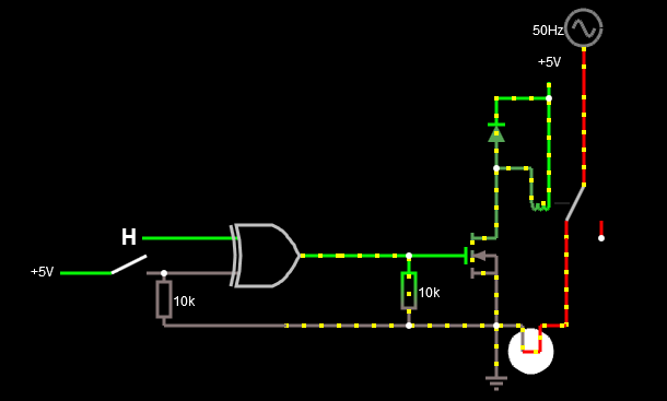
If you want a totally independent switch in case of the microcontroller fails, then you can hook-up an XOR gate for two inputs. The relay will be off when both inputs are the same, and on if the inputs are different. The two inputs are:

  1. Regular switch for manual control.
  2. Output from an MCU for automatic or remote control.

The circuit:

enter image description here

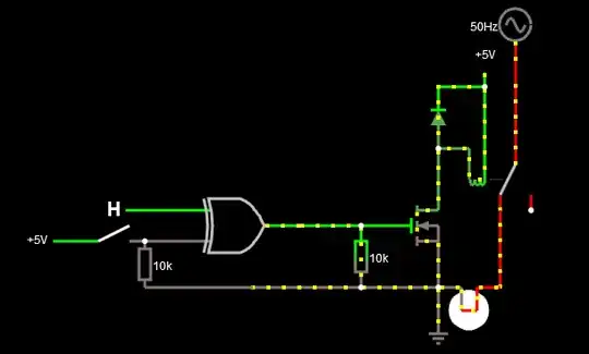
Normally the switch should be open (input B is low just like on the image above) and the N-FET is driven by the MCU pin. When the MCU pin is low, then the XOR gate outputs low because the inputs match(both low) and the relay will be turned off. When the MCU pin is high, the relay will be turned on because the inputs are different.

Now if the MCU crashes and its pin stucks in a state, then there are two cases:

  1. MCU pin stucks in high state and the relay remains turned on. In this case switch will give you an ability to control the relay as follows. If the switch is open then the relay will turned on, and if the switch is closed the relay will turned off.
  2. The MCU pin stucks in low state. In this case an open switch will turn off the relay and a closed will turn it on.

Here is a simulation so you can check the mechanism yourself. The GPIO pin of the MCU can be controlled remotely via Bluetooth, WiFi or the already mentioned 433 MHz module or other suitable technology.


Update requested by OP:

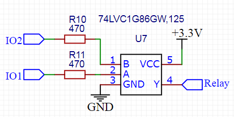
List of 2 inputs XOR gates available at Farnell for example. Here is a particular one from Texas Instruments also available at Farnell.


Some remarks about safety. If you decide to switch mains voltage then it is recommended to switch the hot mains wire rather than the neutral.

The best would be to use an SPDT relay to make sure and switch hot and neutral as well.

enter image description here

Instead of a MOSFET you could use an opto-isolator to isolate the digital circuit and the manual switch from the relay and mains.

Always use proper sealing, do not let open bare metal surfaces. Keep in my that dealing with mains voltage is always highly dangerous.

Bence Kaulics
  • 7,843
  • 8
  • 42
  • 90
3

I believe your original statement may be flawed.

The reason I can't use relays is that I also need the switches to be switchable manually

Why not just get a relay with a manual override?

Here is one available from honeywell.

Bence Kaulics
  • 7,843
  • 8
  • 42
  • 90
SeanJ
  • 1,255
  • 8
  • 19
3

A XOR circuit or this somewhat will implement your requirement! enter image description here

  • It work like staircase switches to toggle the bulb from both sides. I am using 2 SN74LVC1G3157DBVR chips. IO1 will connect with a switch, IO2 connect to Pic I/O pin.
  • The only thing that I could not control is to know state of the relay so status of the load is not known to the attached Microcontroller.

enter image description here