This is an "ancilliary answer" [tm]
You say:
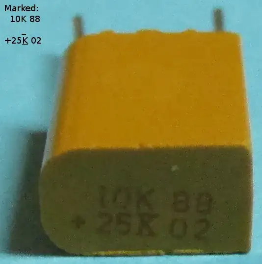
but if i flip it around, it seems like it has a little more capacitance...
Low cost milspec tantalum capacitors from a Hamfest are well worth using if they meet a significant need in an amateur situation where failure (and just possibly conflagration) is acceptable.
Otherwise, solid tantalum capacitors are disasters waiting to happen.
Rigorous design and implementation that guarantees that their requirements are met can produce highly reliable designs. If your real world situations are always guaranteed to not have out of spec exceptions then tantalum caps may work well for you, too.
Good luck with that.
Spehro notes:
The data sheet for Kemet's Polymer-Tantalum caps says (in part) : "The KOCAP also exhibits a benign failure mode which eliminates the ignition failures that can occur in standard MnO2 tantalum types.".
Strangely, I can find nothing about the "ignition failure" feature in their other data sheets. these particular tantalum caps
Solid Tantalum electrolytic capacitors have traditionally had a failure mode which makes their use questionable in high energy circuits that cannot be or have not been rigorously designed to eliminate any prospect of the applied voltage exceeding the rated voltage by more than a small percentage.
Tantalum caps are typically made by sintering tantalum granules together to form a continuous whole with an immense surface area per volume and then forming a thin dielectric layer over the outer surface by a chemical process. Here "thin" takes on a new meaning - the layer is thick enough to avoid breakdown at rated voltage - and thin enough that it will be punched through by voltages not vastly in excess of rated voltage. For an eg 10 V rated cap, operation with say 15V spikes applied can be right up there with playing Russian Roulette. Unlike Al wet electrolytic caps which tend to self heal when the oxide layer is punctured, tantalum tends not to heal. Small amounts of energy may lead to localised damage and removal of the conduction path. Where the circuit providing energy to the cap is able to provide substantial energy the cap is able to offer a correspondingly resistant low resistance short and a battle begins. This can lead stp smell,smoke, flame, noise and explosion. I've seen all these happen sequentially in a single failure. First there was a puzzling bad smell for perhaps 30 seconds. Then a loud shrieking noise, then a jet of flame for perhaps 5 seconds with gratifying wooshing sound and then an impressive explosion. Not all failures are so sensorily satisfying.
Where the complete absence of overvoltage high energy spikes could not be guaranteed, which would be the case in many if not most power supply circuits, use of tantalum solid electrolytic caps would be a good source of service (or dire department) calls. Based on Spehro's reference, Kemet may have removed the more exciting aspects of such failures. They still warn against minimal overvoltages.
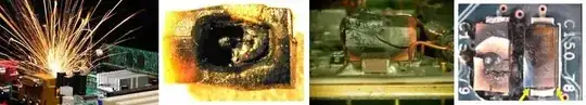
Some real world failures:
Wikipedia - tantalum capacitors
- Most tantalum capacitors are polarized devices, with distinctly marked positive and negative terminals. When subjected to reversed polarity (even briefly), the capacitor depolarizes and the dielectric oxide layer breaks down, which can cause it to fail even when later operated with correct polarity. If the failure is a short circuit (the most common occurrence), and current is not limited to a safe value, catastrophic thermal runaway may occur (see below).
Kemet - application notes for tantalum capacitors
- Read section 15., page 79 and walk away with hands in sight.
AVX - voltage derating rules for solid tantalum and niobium capacitors
For many years, whenever people have asked tantalum capacitor manufacturers for
general recommendations on using their product, the consensus was “a minimum
of 50% voltage derating should be applied”. This rule of thumb has since become
the most prevalent design guideline for tantalum technology. This paper revisits this
statement and explains, given an understanding of the application, why this is not
necessarily the case.
With the recent introduction of niobium and niobium oxide capacitor technologies,
the derating discussion has been extended to these capacitor families also.
Vishay - solid tantalum capacitor FAQ
. WHAT IS THE DIFFERENCE BETWEEN A FUSED (VISHAY SPRAGUE 893D) AND STANDARD,
NON-FUSED (VISHAY SPRAGUE 293D AND 593D) TANTALUM CAPACITOR?
A. The 893D series was designed to operate in high-current applications (> 10 A) and employs an “electronic” fusing mechanism. ... The 893D fuse will not “open” below 2 A because the I2R is below the energy required to activate the fuse. Between 2 and 3 A, the fuse will eventually activate, but some capacitor and circuit board
“charring” may occur. In summary, 893D capacitors are ideal for high-current circuits where capacitor “failure” can cause system failure.
Type 893D capacitors will prevent capacitor or circuit board “charring” and usually prevent any circuit interruption that can be associated with capacitor failure. A “shorted” capacitor across the power source can cause current and/or voltage transients that can trigger system shutdown. The 893D fuse activation time is sufficiently fast in most instances to eliminate excessive current drain or voltage swings.
Capacitor guide - tantalum capacitors
- ... The downside to using tantalum capacitors is their unfavorable failure mode which may lead to thermal runaway, fires and small explosions, but this can be prevented through the use of external failsafe devices such as current limiters or thermal fuses.
What a cap-astrophe
I was working at a manufacturer that was experiencing unexplained tantalum-capacitor failure. It wasn't that the capacitors were just failing, but the failure was catastrophic and was rendering PCBs (printed-circuit boards) unfixable. There seemed to be no explanation. We found no misapplication issues for this small, dedicated microcomputer PCB. Worse yet, the supplier blamed us.
I did some Internet research on tantalum-capacitor failures and found that the tantalum capacitors' pellets contain minor defects that must be cleared during manufacturing. In this process, the voltage is increased gradually through a resistor to the rated voltage plus a guardband. The series resistor prevents uncontrolled thermal runaway from destroying the pellet. I also learned that soldering PCBs at high temperatures during manufacturing causes stresses that may cause microfractures inside the pellet. These microfractures may in turn lead to failure in low-impedance applications. The microfractures also reduce the device's voltage rating so that failure analysis will indicate classic overvoltage failure. ...