3

I have a 8x8x8 lcd/led/button module (tm1638 chip) connected to my Arduino r3. When I attach a pump (GPH350, 1.5A, 12V to the same power supply (12V, 5A) - my display stops working correctly (only part of the text is displayed) (and sensor report invalid data).

The same setup works without the pump or when the pump is running on a separate power supply.

Is this because my power supply isn't strong enough? Isn't 5A enough? Is there anything I can except running 2 PSUs or using a more powerful one?

Can I prevent this by using a capacitor? How do I find out what size it should be?

Photo v1

Photo v2

Edit: I've changed my curcuit, added a 1N4148 and a larger capacitor. And there is a new photo.

Edit 2: Since there seems no way around buying an oscilloscope and the good people who've helped me on this are running out of ideas I decided to abort the mission. Thanks for all the help.

schematic

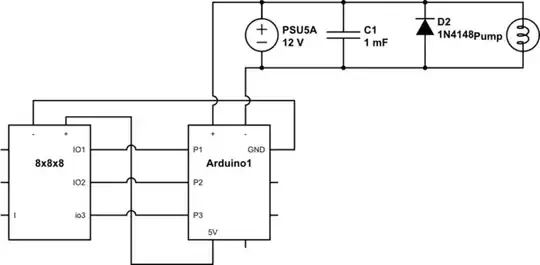
simulate this circuit – Schematic created using CircuitLab

PhilW
  • 215
  • 2
  • 7
  • 1
    How are your grounds set up? – Matt Young Jan 21 '14 at 19:06
  • A block diagram and schematic would be helpful. – Matt Young Jan 21 '14 at 19:25
  • I've added a schematic, I hope it helps. It's simple: Arduino and Pump share one PSU, 8x8x8 module is connected to Arduino. – PhilW Jan 21 '14 at 20:55
  • 1
    Regarding the possible duplicate - this could be it, but shouldn't the MCU recover after the high current device has started? I mean the voltage shouldn't change after that? – PhilW Jan 21 '14 at 20:58
  • Is there some sort of switch in series with the pump? – Tut Jan 21 '14 at 21:05
  • @tut No switch, originally I had a relay to turn the pump and off, but because of my problem I removed all other components. – PhilW Jan 21 '14 at 21:07
  • @PhilW now that you've added the schematic and other information, I can't really say it's a duplicate. – Phil Frost Jan 21 '14 at 21:58
  • @PhilFrost I've added a capacitor and a diode, but that didn't help - could you take a look at my new curcuit/photo (I'm not sure I drew it correctly)? Thank you! (oh I also tried putting the 12V between the two on the breadboard) – PhilW Jan 23 '14 at 13:38
  • @Tut thanks - I wasn't sure and yes I did fry one them... Is it the right kind of diode though? I have 1N4148 and 1N5819 here – PhilW Jan 23 '14 at 13:43
  • @PhilW I don't see anything obviously wrong. Have you checked that the 12V supply is still 12V even when the pump is running? An oscilloscope would be really useful here, so we can see if there's noise somewhere. Without it, we can't do much better than a lot of guessing. – Phil Frost Jan 23 '14 at 13:46
  • 1
    Use the 1N5819. The peak current will occur when the pump shuts off and will equal the on-current of the pump and immediately start to decay. The 1N4148 appears to have a max peak of around 400 mA which is too small. The 1N5819 can be pulsed up to 25A. The 1N5819 is schottky so is faster which is also to be recommended. – Tut Jan 23 '14 at 13:51
  • Just for kicks, measure the 5V supply into your display. I don't know what the Arduino has to spare for outside boards, but it probably isn't a lot and all those LEDs could draw significant current. If it is low, you may want to consider a separate 5V supply for it. A little noise on a board with a marginal supply can cause all sorts of miss-adventures. – Tut Jan 23 '14 at 14:08
  • @PhilFrost Thanks - I've measured a steady 12.56V - Unfortunately I don't have an oscilloscope yet - I'll need to do some research what I need. Feel free to suggest one, but I also understand this is not the right place for that. – PhilW Jan 23 '14 at 16:27
  • @Tut I've measured between about 5.03V and I added a external PSU (which does either 4.5V or 6V). It does the same thing: Somewhat random data on the 7 segment display, sometimes it shuts off completely. From what I read on the link (see Q, top) a fully lit module draws 127mA - I should be fine (900mA is the limit for the 5V pin, AFAIK). I guess I'm stuck - without a scope :-/ Thanks again for your help – PhilW Jan 23 '14 at 16:36

1 Answers1

3

Troubleshooting this type of thing requires an oscilloscope, which I'm guessing you don't have. However, based on your photo and schematic, we can make a couple educated guesses, which might be good enough.

Firstly, you probably want some capacitance across the 12V supply. The supply can respond to changes in current only so fast. A capacitor provides a reserve of energy to help fill in these sudden changes in demand. The capacitor also helps to absorb transient energy spikes such as those that might come from the pump motor.

How big? More is better, until you have enough, then it's just wasted money. Usually an electrolytic capacitor is used, maybe as much as 1000µF. The value isn't terribly critical so use what you have on hand. I'd put the capacitor right where the wire from the supply split to go to the pump and the Arduino.

Secondly, you may need a flyback diode across the pump, if it doesn't have one internally already. If you don't know, it can't hurt to add another. Put this as close to the pump as possible. Put the cathode on the + side of the supply, and the - on ground, such that it's normally reversed biased. If you get it backwards, you will know by the smoke.

Phil Frost
  • 57,310
  • 18
  • 145
  • 267
  • I've just tried by adding 4x 200uF capacitors in series, unfortunately no change - I will add more later. I don't have a flyback diode yet, I have to see if I can get one. My question was marked as a duplicate now, is it though? I cannot tell and the answer given there doesn't help me as it isn't clear to me how I'd wire it correctly. I'll check back in about 10hrs. – PhilW Jan 22 '14 at 00:32
  • @PhilW I'd suggest you spend some time researching the concepts mentioned in the other question, and come back with specific questions where you don't understand. There are a lot of things that could be causing your problems, but we don't have enough information to know specifically what. People here can help you understand how things work, but ultimately you will have to do the troubleshooting. It's just not feasible any other way. – Phil Frost Jan 22 '14 at 01:52
  • 1
    @PhilW also, putting capacitors in series decreases their effective capacitance. You want them in parallel, if anything. – Phil Frost Jan 22 '14 at 01:53
  • @Tut I'm not sure what you mean by running separate wires to the power supply, I've added a photo from before I added capacitors - can you point it out to me? I just can't see a different way to run my wires :/ – PhilW Jan 22 '14 at 10:01
  • @PhilFrost I now changed the capacitors to a parallel configuration (thx), didn't help unfortunately - would you try and add more (800uF)? I'd like to try everything else before I order more parts (flyback diode). Regarding the duplicate: Of course, I will try and do what I can to debug and understand this, my problem is that I don't know how I would wire my setup differently according to your diagram in your answer in the other question. I cannot route 12V through my arduino. Then there's grounding - I've tried connecting the GND from the 8x8x8 with the PSU, this didn't help (worse). – PhilW Jan 22 '14 at 10:04
  • @PhilFrost (cont'd) so from what I can tell (with my limited knowledge), all I can do is add more capacitance and add a flyback diode, correct? Thanks again for your help and insight. – PhilW Jan 22 '14 at 10:09
  • @Tut Thanks, yes I've ordered some Schottky diodes. But I still don't follow what you mean by a separate pair - don't I have that already (http://i.imgur.com/l64bW8w.jpg)? I made a little diagram - maybe this helps: http://i.imgur.com/WS3kKU2.jpg
    • I think what I currently have is "1", where +/- from both MCU and pump come together at the same point with the 12V source. I only see two other options..? Thank you for your patience :)
    – PhilW Jan 22 '14 at 14:36