This question relates to my earlier question on how to wire an optointerruptor:Figuring out wiring of optical encoder
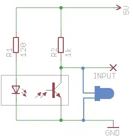
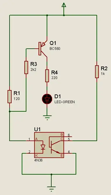
I was able to get the optointerruptor working using the circuit below. I wanted to add an LED to indicate sensor state. The blue LED in the image below is what I tried initially. However this doesn't work: the result is that with the LED connected, it will light and show state, but the input to the microcontroller (an Arduino) stops showing correct state. This is totally confusing. Why would the LED interfere what the Arduino can read (as a digitalRead)?
I've breadboarded the circuit and it seems to work - but in my actual project it doesn't. As a starting point in figuring this out, is the circuit below wrong?