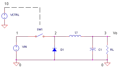
3

Here is the figure: enter image description here

All tutorials have an inductor in smsp-buck. But when I simulate without an inductor I see a similar plot. Why not use only a capacitor?

user16307
  • 12,049
  • 52
  • 184
  • 320

3 Answers3

3

A buck converter changes a high input voltage to a lower output voltage. It does it with a certain amount of grace and the result is fairly good with medium levels of ripple on the output voltage that are related to the switching frequency.

Without an inductor switch SW1 connects the input voltage to the output voltage and pushes a theoretically infinite amount of current into C1. I don't need to say anything else because to do so would be insulting.

You also ask, in a comment "Why not to use a capacitor in series instead". The buck convertor passes DC current (with some ripple) through to an output load. A capacitor in series will become charged to the line voltage and any further attempts to push DC through it will fail.

Andy aka
  • 456,226
  • 28
  • 367
  • 807
  • sorry wanted to say why not filter the hogh freq with an inductor instead? not series but in parallel. so the inductor is to protect capacitor? – user16307 Nov 20 '13 at 12:15
  • That doesn't make sense - why not add a picture of what you mean to your question or a link in a comment. – Andy aka Nov 20 '13 at 12:34
  • OK try thinking about it this way - a clutch on a car slips the speed to the wheels but if the wheels were directly connected to the engine and the clutch was somewhere else how would that work properly. The inductor is like a clutch - it eases the voltage onto the output capacitor without big jerks and the possibility of stalling the engine (equiv to a short circuit.) – Andy aka Nov 20 '13 at 12:36
  • another commentator said ""The inductor in addition to the capacitor is needed to filter the high frequency component of the output. and you say "it is to prevent the capacitor. my question is normally filtering high frequency is done by a low pass filter (by using a capacitor). he says inductor is for filtering and im wondering if it is the only reason why inductor is used to filter? what u say makes more sense to prevent the capacitor. but still i didnt get it why. – user16307 Nov 20 '13 at 12:38
  • "It is to prevent the capacitor" doing what? I don't think I understand. The slipping clutch (resistor) and the wheels (capacitor) form a low pass filter due to the clutch (when slipping) providing near-constant torque to the wheels and the wheels providing inertia. The inductor is a refinement on the resistor but still forms a low pass filter. – Andy aka Nov 20 '13 at 14:31
  • The inductor is basically needed to not fry the capacitor with excessive ripple current. With no coil and a really good cap, you could make a crappy buck converter without a coil. Adding the coil prolongs life and improves performance for little cost. – avl_sweden Aug 17 '15 at 16:44
  • 1
    @avl_sweden without inductance it's not a buck converter. Without an inductor I'd call it a mess. – Andy aka Aug 18 '15 at 07:03
  • @Andyaka "Without an inductor switch SW1 connects the input voltage to the output voltage and pushes a theoretically infinite amount of current into C1". This sounds like you're implying that C1 would breakdown because the current going into it could become infinite; I find this sentence confusing. Could you elaborate? I don't think it would be a problem to have a capacitor in parallel with the input and output voltage. – Klik Oct 07 '16 at 15:23
  • 1
    @klik current theoretically is infinite because current in a capacitor is proportional to change in voltage with respect to time. So you put a step change in voltage across a cap and theoretically you get infinite current in order to charge that capacitor infinitely quickly. In reality that can't happen but, in the context of this question it needs to be said. – Andy aka Oct 07 '16 at 17:43
2

How is the current through a capacitor defined? --> Ic=C dUc/dt. What does that equation tell you? If the voltage across the capacitor changes in a short period of time (dt-->0) such as load changes or first time turning on the power supply, then Ic will be very big (a current spike). The current however cannot change in an inductor rapidly: Ul= L dIl/dt. The inductor prevents the current spike. Now when the switch is closed, a magnetic field is built by inductor. When the switch opens, there is no current flow through the inductor anymore. Magnetic field will collapse. A change in current will create a voltage spike. How do we prevent this? Since the polarity across the inductor changes, the diode will conduct providing a current path for the inductor.

Omid
  • 21
  • 2
2

The LC Combination as in the figure in question is a Low Pass filter. The inductor in addition to the capacitor is needed to filter the high frequency component of the output. Also, the inductor stores energy, so that once SW1 open up, then Inductor should store enough energy to flow a current through the diode(freewheeling). If you removed the inductor, then the diode will be reverse biased, and nothing will happen. Capacitor will just discharge to output.

Sherby
  • 2,356
  • 6
  • 27
  • 46
  • You say "The inductor in addition to the capacitor is needed to filter the high frequency component of the output." Why not to use a capacitor in series instead? – user16307 Nov 20 '13 at 11:41
  • 1
    I believe Andy answered that question very well below. Inductor does not allow current change. Think of it like a Capacitor, but for current. So both are need for the whole LC to behave as a Filter. You could also look up on the mathematical model for the LC combination. – Sherby Nov 20 '13 at 13:44