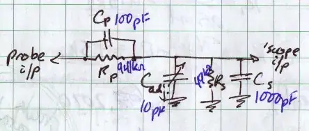
I am trying to design an oscilloscope/BNC input circuit for a side project and to learn more about filters.
The requirements are:
- 150-200 MHz -3dB bandwidth
- 1 megohm impedance
- 50 ohm termination option (I can omit this if it causes problems.)
- Can be switched between 2x and 20x attenuation
- Measures up to 80Vpk (160Vp-p), tolerates up to 400Vpk (800Vp-p) (5Vpk on 50 ohm mode.)
I designed a neat circuit that allowed switching between 2x and 20x attenuation while keeping 1 Mohm (or thereabouts) attenuation, as below:
                499k        442k
( Input ) -----/\/\/---+---/\/\/---+----- To JFET input buffer
                       |           |
                       /           /
                  499k \           \ 49.9k
                       /           /
                       |           |
                       +---+   +---+
                           |   |
                            \       relay to switch
                             |     attenuation 2x/20x
                            ---
                             -
(All resistors 1%.)
However, then I learned oscilloscopes have input capacitance, and I'm not sure how to add it. Also, if I want the input to tolerate 400Vp-p swing but on the wrong input range (2x attenuation leaving 200Vp-p to damage the inputs of the JFETs), I couldn't use diodes as the lowest capacitance I found was 0.13pF for an RF diode, which would limit me to about 612kHz for two diodes (one to each rail, reverse biased.)
