1

I've got a TI MAX3237 5 TX / 3 RX transceiver (TI datasheet, Maxim datasheet) set up as follows: Circuit diagram

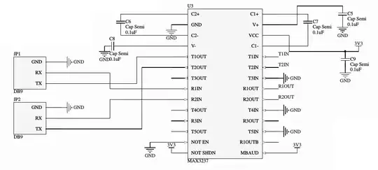
The supply is 3V3 from a BeagleBone Black, measured at 3.35v. The CMOS level inputs and outputs (T1IN, T2IN, R1OUT, R2OUT) are taken out to headers, where I can connect them as desired.

The receive part of the transceiver is working great. I can put an RS232 level signal on R1IN / R2IN and receive a level shifted version on R1OUT / R2OUT. I've confirmed this both by looking at it with a scope, and by actually hooking the outputs up to a UART and receiving data.

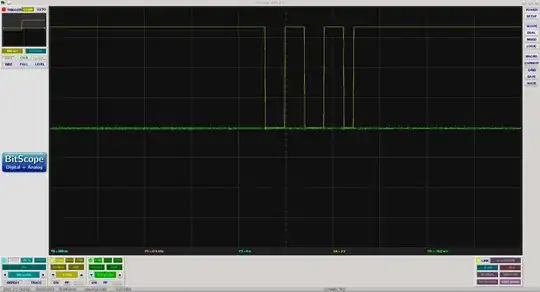
The problem is transmission. Putting a signal on T1IN results in nothing on T1OUT - literally. The signal level is at 0V. Channel 1 (yellow) is the UART output, and channel 2 (green) is T1OUT. (this is with the output also connected to a RS232 receiver - with the receiver disconnected the result looks the same)

enter image description here

I've measured V+ and V-, which seem to be at 2.37V and -2.37V respectively; while the datasheet claims they should be 5.5V and -5.5V. Could this be the problem? If so, what could be causing it? I'm using non-polarized ceramics as my capacitors.

cb22
  • 11
  • 2
  • If you put a signal on T1IN then you will get nothing on T2OUT - maybe you need to correct something in your question? – Andy aka Oct 01 '13 at 12:22
  • @Andyaka - thanks, edited. It was meant to be T1OUT – cb22 Oct 01 '13 at 12:28
  • There is something definitely wrong if the charge pumps are not generating 5.5 V according to the maxim data sheet - they say it will produce +/- 5.5 V on supplies from 3.3 V to 5 V. – Andy aka Oct 01 '13 at 12:36
  • Have you got MBAUD set correctly for your data rate - This device operates at data signaling rates of 250 kbit/s in normal operating mode (MBAUD = GND) and 1Mbit/s when MBAUD = VCC. It should be OK high even at low data rates but it's worth a try. – Andy aka Oct 01 '13 at 12:41
  • Check you haven't got /SHDN at ground too. – Andy aka Oct 01 '13 at 12:44
  • Measured /SHDN and /EN on the chip, both are at the correct values (3.3V and 0V respectively). Also cut the trace from MBAUD to VCC and set it to ground, nothing changed. Starting to think I have a fried chip (ESD perhaps?) - but it's strange that RX still works. – cb22 Oct 01 '13 at 12:59
  • I tend to agree with you about it being fried unless there is something around the charge-pump caps that's causing an issue - maybe a short or open circuit? – Andy aka Oct 01 '13 at 13:01
  • Hah! Found it. Turns out the pad with C1+ didn't reflow properly. When I originally probed it to test continuity, I pressed down a fair bit on the lead, pressing it into the pad and resulting in a connection - and fooling me. V+ and V- are now at their nominal voltage, and everything works great. Thanks! – cb22 Oct 01 '13 at 13:30
  • coolio chap and good luck – Andy aka Oct 01 '13 at 13:39

0 Answers0