Please bear with me here. I haven't had to do much circuit design since my MechE days in college, so I'm very rusty.
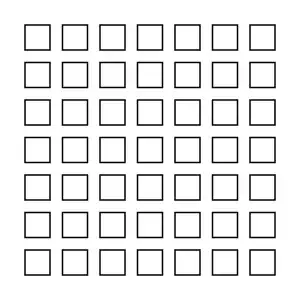
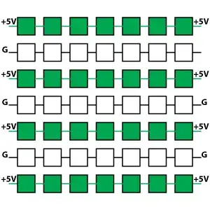
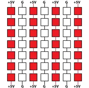
I'm working on a project where I need to be able to take a grid of conductive squares (say a piece of perfboard) and create alternating lines of continuity. In one moment there would be horizontal continuity, and in the next moment there would be vertical continuity, as shown:
I'm getting stuck on figuring out how to make this work. I've been going back and reviewing simple transistor switches, but those seem to be concerned with switching current across a load, whereas what I need to do is switch the high (+5V) signal continuity, without necessarily causing any current unless there happens to be a component touching one of the "high lines" and "ground lines" at a given moment.
One of the main challenges, as you can see, is that it's not enough to simply change where the voltage is applied at the edges. Continuity between individual grid squares has to be broken and created each time the lines switch from horizontal to vertical.
Any and all help would be much appreciated. Thanks.
EDIT:
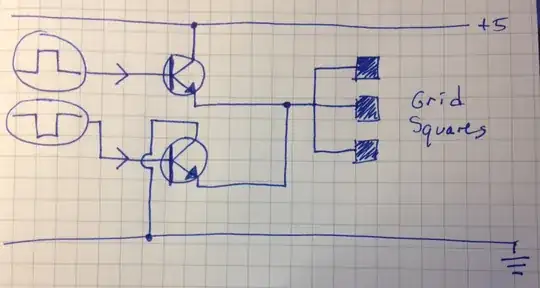
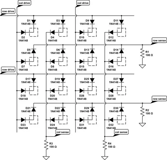
Based on Dave Tweed's square wave idea, I sketched out the following circuit. This is my best guess about what you meant for using two out-of-phase square waves. Is this correct? If I understand correctly, this will result in the connected squares alternating between +5V and Gnd? (Sketch below)
If this is correct, I assume that for the other "switching" squares, I would duplicate this circuit and reverse the signal inputs? Thanks again.