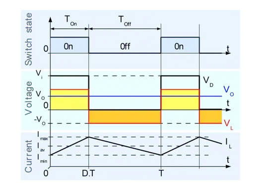
The average voltage at point L is a pulsating square wave of amplitude \$V_g\$.
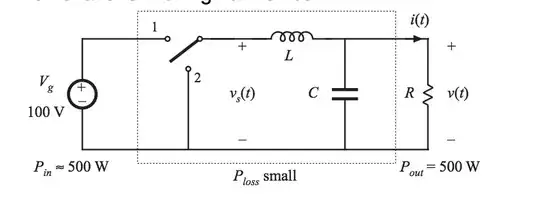
The inductor will limit the current flowing by the usual inductor formula:
\$ V_L = L \dfrac{di}{dt} \$
When the switch is in position 1, current ramps up in the inductor:
\$ V_L = V_g - v(t) \$
\$ V_g - v(t) = L \dfrac{di}{dt} \$
\$ di = \dfrac{[V_g - v(t)] \cdot dt}{L} \$
When the switch is in position 2, current ramps down in the inductor:
\$ V_L = 0 - v(t) \$
\$ -v(t) = L \dfrac{di}{dt} \$
\$ di = \dfrac{-v(t) \cdot dt}{L} \$
The net result of this is a triangular current waveform. Since the capacitor is constantly being charged by the inductor, its voltage will be the average of the pulsating square wave with triangular ripple voltage induced across its ESR by the triangular current waveform coming from the inductor.
The energy storage of the inductor is what allows the converter to work; in fact, inductive energy storage is how the majority of PWM-based switching converters are able to do what they do.