This requirement can be well met using sail winch servo motors, controlled by SPI or I2C servo controllers, or better yet, radio controlled 4-channel or better servo controllers such as used for RC toys.
What?
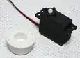
- Sail winch servo motors are designed for one, or several turns, based on a servo control signal. They are specifically used for rolling and unrolling a string or cord, such as used in radio controlled model sailboats or even full scale real ones. PID coding is not required, that is taken care of within the servo's internal electronics - your code just specifies "go to 75% position" to get a certain turns of rotation.
- For example, the HobbyKing SW4805-6PA supports 6 full turns of the winch wheel, in a tiny 45 gram device, for under $8.
- A hobby servo control signal is a 3.3 to 5 Volt, varying pulse duration signal representing minimum to maximum positions with a (typically) 1.0 to 2.0 ms pulse every (typically) 20 milliseconds. This can be achieved through a 50 Hz PWM with duty cycle varying from 5% (minimum position) to 10% (maximum position). Technically, some sources insist that this signal should not be called PWM, but PDM (Pulse Duration Modulation), since the 50 Hz signal cycle can be varied a lot, often from 25 to 100 Hz, so long as the pulse duration remains between 1 and 2 ms each.
- Inexpensive Servo drivers are available, supporting a number of servo control channels (i.e. motors) per unit, 4 or more being common. These interface with microcontrollers using SPI, I2C, or even interface with a PC using USB. This means the PDM servo signals are offloaded from your microcontroller, and generated internally by the multichannel controller.
- For example, the Adafruit 16-Channel Servo Driver, at under $15 each, can be cascaded to control up to 992 servo motors using just 2 lines on the microcontroller.
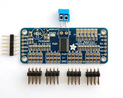
- Alternatively, make such a servo controller yourself using a multichannel PWM driver IC such as PCA9685.
How?
- Obtain a bunch of sail winch servos. Fabricate or buy larger capstans (winch wheels) if the string movement range required is larger than offered by the default capstan in the maximum number of turns. Use transparent monofiber plastic fishing line to suspend the spheres from the capstans.
- Obtain or build servo driver boards that support multiple channels each, and can be cascaded in series.
- Control a group of servo drivers each with one set of GPIOs from the microcontroller. The servo controller takes care of generating servo PDM, so your code needs to only send change-of-position information when required
- Power the servo motors in groups, using RC hobby UBECs, i.e. integrated switching regulators that can support huge currents for driving motors, available at very low prices due to economies of scale. The servo control lines themselves do not need much power, servo motor power lines are separate.
Why?
- Cost: A servo motor is a real bargain compared to a conventional motor, the H-bridge / motor controller for each, the microcontrollers to run PID code (even if you run multiple PIDs per microcontroller), and the position feedback mechanism. The servo has all this built in.
- Convenience: If the objective is to get the system operational, rather than to spend months or years perfecting PID algorithms, positional feedback mechanisms, motor control MOSFETs circuits, and associated circuitry, then a solution like this, using mass-market, easily available and reasonably priced devices, is the solution.
- Ease of development: Individual blocks of the design can be built, tested and then set aside for final assembly. Everything does not need to be built at once.
- Reliability: With a modular implementation such as described above, any failure to any element does not require a full shut-down and comprehensive diagnostics. The affected motor, servo driver, or microcontroller board can be replaced using pre-built parts, and the system re-started pretty quickly. Keeping spares is also not a big issue in this approach.