For a project that I've been working on, I want to drive a couple of ICs and several LEDs from an ~12V supply (lead-acid battery). I think the whole thing should draw about 100mA, so I didn't really want to use a linear regulator: I shouldn't need to dissipate 1.2 watts just to drive a couple of LEDs!
So I designed things with a buck converter based on an MC33063 chip and I've been breadboarding to see how everything works. Unfortunately, what I should have realised before is that I can't avoid discontinuous mode with such low current draw and such a large step down in voltage. Trying 3.3V output, the regulator switches on and off at about 500Hz giving an unpleasant sounding buzz from the inductor and a spectacularly poor output waveform (~1V ripple). I'm using a 50 Ohm load, which should draw about 50mA.
Am I just "Doing It Wrong"? If so, what's the sensible solution I've missed? I guess I could follow the buck regulator with an LDO to filter the power rail, but that's getting a bit ridiculous and won't help with the unpleasant sound from the inductor being switched on and off. Ideas?
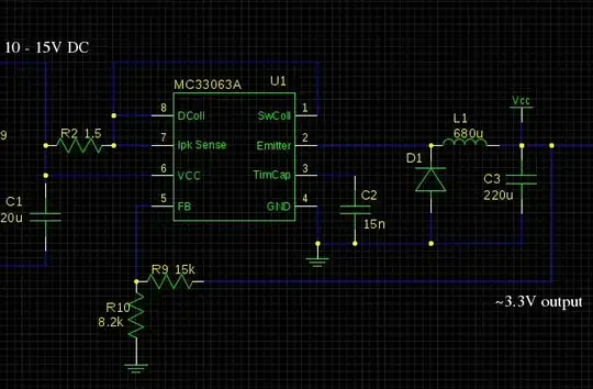
There's not much to see, but the buck portion of the circuit is just this:
 .
.
When breadboarding, I've replaced R2 with a dead short because I don't have any low value through-hole resistors, but I shouldn't imagine that makes much difference (since it's a high current cut-out). D1 is an SR104 Schottky.