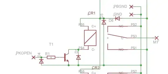
The transistor and the resistor might be needed because the input can not supply enough current to drive the relay. D4 protects the transistor from a negative voltage at the input.
D6 protects the transistor from a negative power, and prevents spikes to enter the power rails.
A relay that is switched off produces a current pulse that must be dissipated somewhere, otherwise it will destroy the transistor. D1 could be intended to protects the transistor against this pulse, but IMO it is placed wrong: the diode should be in parallel with the relay coil.
I can't see any purpose for D3, unless it has something to to with components connected to the vertical wire that are not shown.
All in all this looks like a circuit produced by a committee with too much open agenda's and some closed ones too.
