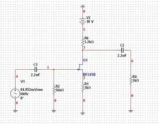
As Beta changes from BJT to another, Vp and Idss also change from a JFET to another, but how can you assure that when the JFET changes, the Q-point does no change greatly?
Asked
Active
Viewed 886 times
1
-
Is the device is already connected in a circuit and needs changing or are you designing a circuit using a JFET that might need changing in the future? – JIm Dearden May 29 '13 at 21:04
-
It's a basic lab experiment I am being asked about this particular point while designing common source amplifier. I would like to know how do Rs and RD affect the operation point as compared to other parameters such as Beta in BJT. This is the circuit http://s8.postimg.org/hh16czcb9/untitled.jpg – Anas Elgaood May 29 '13 at 21:19
-
I'm going to repeat myself and think out loud about a different way to ask the question: Beta changes from one BJT transistor to another. In JFET Vp and IDss also change from one JFET to another. How can we assure that these changes won't affect the Q-point greatly? Are there any particular measures to be taken to prevent the Q-point from slipping into unwanted regions? -It isn't mentioned in the question but since we're using the configuration as an amplifier, how do we stay in the linear region of operation? – Anas Elgaood May 29 '13 at 21:32
1 Answers
1
Generic question, generic answer: By using negative feedback.
With a BJT, this can be done by adding an emitter resistor, or creating a path from collector to base. Similar techniques can be used with other types of devices.
Dave Tweed
- 172,781
- 17
- 234
- 402
-
in terms of JFET's regions, how can I achieve this in order to maintain the Q-point at an acceptable point to allow unclipped swing? – Anas Elgaood May 29 '13 at 21:21
-
Don't allow such as small Vds that it goes into the ohmic region. So your bias has to take the gate sufficiently negative that you're somewhere near pinchoff, and so there is a decent drain-source voltage, far from the ohmic region. – Kaz May 30 '13 at 00:15
