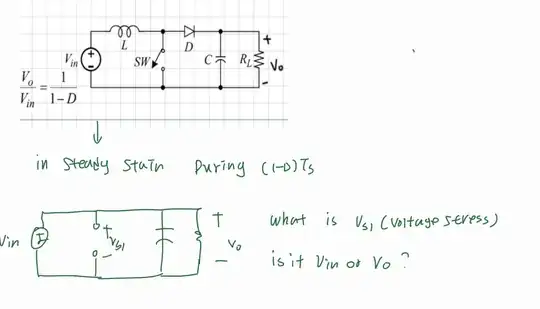
I know the answer is Vs=Vo, by simulation. BUT I don't know why. In steady state inductor is gonna be short. And Vs is parallel with Vin and Vout. Can you tell me what is wrong?
Asked
Active
Viewed 38 times
0
-
I recommend you take a look at the tutorial I built on switching converters. It will show you the switching steps for this boost converter. – Verbal Kint Mar 30 '24 at 08:35
1 Answers
0
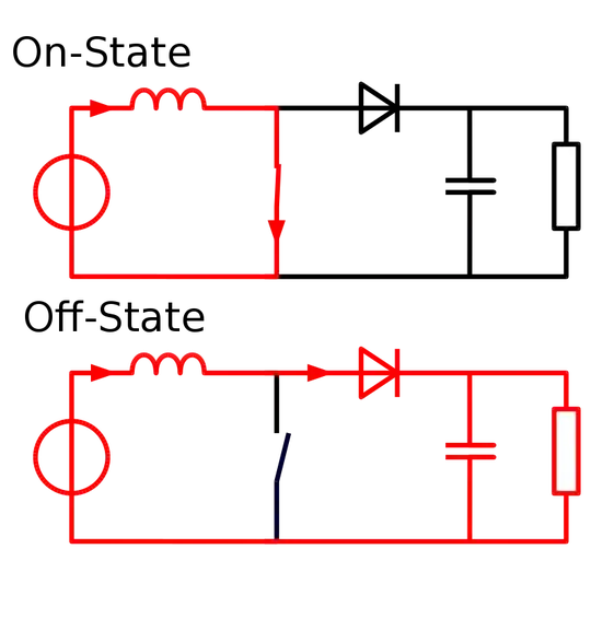
The converter you drew is a boost converter, not a buck converter. I don't know why you shorted the inductor in the second phase. In that phase, the inductor is not shorted, and the voltage across the switch is \$V_O\$ (assuming an ideal diode with zero voltage drop).
 Image taken from Wikipedia: Boost converter.
internet
- 544
- 1
- 3
- 13
-
-
@cocoromina I think I now understood your sentence regarding the inductor being shorted in steady state. That would be true if the converter stayed in the second phase forever, but that isn't the case as it is a switching converter that alternates between phase 1 and phase 2. – internet Mar 30 '24 at 07:23
