2

The subject seems to be very easy and simple but performing research and looking at the real devices I get more and more questions.

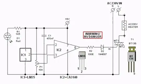
Let's take this article as a basis. It has the following circuit:

enter image description here

explained in the article. The problem I get is related to the "heater" in the circuit. And, what's not that funny, with resistance in general.

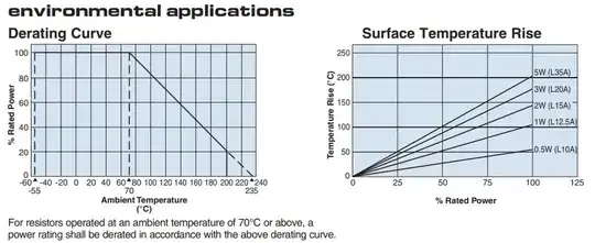
If we look into the resistor datasheets it seems rare one states the operating temperature for the resistor. Second, it shows the "derating curve":

enter image description here

where we may guess what operating temperature is assumed to be, but showing the plain resistance value for temps below 70 C. It is clear is it not actual resistance curve, but kind of misleading. Edit: and I made a mistake thinking that it is resistance derating, but it is power derating.

The device I am going to prototype will consist of several identical 2 Watt resistors in series. I have similar available device on hand, my calculations show that power rating of the resistors involved is twice the expected during operation, current flowing through the resistor chain is expected to be 0.05A @ Vrms=155 V, but for some reason the same BT136 is used, and it makes me stuck. The BT136 is 600V/4A device, and seems to be severe overkill for the device utilizing 275VAC (max) with 0.07A current. Is it just a coincidence of someone copy-pasting, or it has some very specific sense I do not see? Using smaller triac will save some board space.

The only viable idea I have is that at -40C (industrial temp) resistor chain resistance may be less than nominal declared in the datasheet and marked on its body, thus startup current will be more than operating one, but I am unable to find related information in the (power) resistor datasheets.

Any advice and insight is appreciated.

Update: Z0109MN seems to be appropriate?

(not related to question: there's a problem with series resistor circuit - if one of resistors starts failing increasing its resistance the power on it may get several times higher than planned, causing more damage, but then will decrease back as resistor keeps opening).
Anonymous
  • 7,052
  • 1
  • 14
  • 45
  • I'm no expert on these devices. But it does sound like the BT136 is overkill for you. You need only low-100's of mW dissipation when on. So smaller packaging would seem possible. The I^2s (fusing) spec would be something else to consider. The BT136 seems to suggest 17 A for 10 ms maximum. I can't imagine you needing anything like that. So a lower fusing spec would likely also be fine. What device do you have in mind, though? Perhaps that's important to add to the question. – periblepsis Mar 26 '24 at 18:52
  • This is really a heater for the industrial equipment, expecting to work in extended temp range and support internal chassis temp at say 20 C. I also considered the FET-based heater, but resistor-based is much simpler in terms of circuitry and powering. – Anonymous Mar 26 '24 at 18:54
  • Has nothing to do with your question. But you have made me curious. Are you trying to regulate circuit temperature and keep it relatively stable regardless of environment? Or actually heating up something mechanical, not electronic? Or regulate interior air temperature of some box? (My curiosity only.) I'll +1, regardless. It's framed well enough. – periblepsis Mar 26 '24 at 18:59
  • Regulate interior air temp. I assume I can measure temp at several locations in the chassis - at least near the resistors, and at remote location, and then decide using algorithm in the MCU on the pattern of controlling the triac / heating. The heating of the device is expected to function at -40C properly, that's why I highlight it. Thus I do not have circuit yet, I have an idea and similar product, which I investigate (and which is expected to be of decent make). Thanks for upvote :) – Anonymous Mar 26 '24 at 19:04
  • @Anonymous - Hi, The required reference for the images relating to the resistors, seems to be missing. Please add the name & link to the source (webpage, PDF, video etc.), assuming it is online. TY – SamGibson Mar 26 '24 at 21:45

2 Answers2

0

275VAC has a peak voltage of 388 although it is wise to allow some overhead to allow for inductive spikes etc on the supply. 4A is ample rating but that is maximum when mounted on a substantial heatsink. Even so it seems a little over-engineered in terms of current, but I wonder if there are lower-rated devices that would make the circuit ‘better’ in any way. Resistor temperature coefficients are typically quoted in parts per million per degree Celsius, you should be able to find this on the datasheet for the parts you intend to use.

Frog
  • 7,287
  • 1
  • 9
  • 13
  • T.C.R. (Temperature Coefficient of Resistance), right? Can you please give an example for me to be sure I'd use it properly? Let's say 100 Ohm resistor @ -40C? https://www.koaspeer.com/products/leaded-resistors/power-leaded/mos/ – Anonymous Mar 26 '24 at 18:56
  • Resistance appears to differ in hundredths of Ohms per whole temp range. What's about superconductivity at 0 K :( – Anonymous Mar 26 '24 at 19:32
  • Yes that’s right, there won’t be a lot of change; unless it’s a high precision application or extreme temperatures you can usually ignore the drift. – Frog Mar 27 '24 at 19:25
0

Why such overpowered devices?

  1. People use the parts they know.

  2. People use the parts they have. This is especially true in a design for production. It is surprisingly expensive to bring a new component into a well-documented production environment, both during the initial run and for lifetime product support. Also, the cost difference between buying more pieces of one part number versus fewer pieces each of two part numbers might actually be negative.

  3. The article does not state the power level of the heater in the design. Maybe it is intended for a 100-200 watt application. Other than cost and a higher gate current, there is no real downside to using an oversized TRIAC.

If one resistor begins to fail with increasing resistance, the power dissipation will not increase as much as you might think because that increased resistance decreases the current through the string, including itself (if the string is powered by a constant-voltage source).

UPDATE: Responding to a question.

If you have a series string of resistors powered by a fixed voltage source, then the current through the string is given by Ohm's Law, where R is the total resistance of the string. As with any series circuit, 100% of the current goes through 100% of the components 100% of the time. If the value of one individual resistor increases, the total string resistance increases, and the string current decreases. Straight Ohm's Law.

The power in an individual resistor is given by Joule's Law, P = I^2 x R.

As one resistor value increases, the string current decreases, so the current through that increasing resistance decreases. For any changing resistor, start with its new resistance value, add it to the rest of the string, then Ohm's Law to get the current, then Joule's Law to get the power.

Because the operating voltage and the rest of the resistors are constant, I think you can throw a little high school algebra at the two equations and come up with one equation that relates the bad resistor's value to its power dissipation.

Note: In the world of electronic components, nothing is more reliable than a resistor. When running at a low percentage of its rated power dissipation, the odds of a single resistor failure are very low; certainly lower than any active semiconductor component.

AnalogKid
  • 19,998
  • 1
  • 13
  • 32
  • Last statement is not correct IMHO. 12 resistors of 240 Ohms give 1.09 W per resistor (16.2 V @ 0.067 A), but with one resistor failing to 2400 Ohms this resistor now at 3.57 W (93V @ 0.038 A). – Anonymous Mar 26 '24 at 20:54
  • @Anonymous Here's a picture of that power dissipation curve as one resistor gradually increases in resistance. I just had to replace 0000 aluminum wiring (in the ground) that had rapidly increased into failure for similar, though more extreme, reasons. In the curve, one can see that dissipation rapidly increases, very early on. The 2 W rating is exceeded quite quickly. – periblepsis Mar 26 '24 at 21:15
  • @periblepsis this is exactly what I have calculated. If you look further the resistor value then power on the failed resistor starts decreasing - and starting this resistor value the statement holds true, but not on whole the range. – Anonymous Mar 26 '24 at 21:18
  • @Anonymous Of course. You provided a peak and I illustrated that part of it. I'd be more worried about the early onset side of things, since that can quickly exceed the resistor's rating that you mentioned. One answer would be to spec the resistors for twice the peak power. ;) Say, 10 W ceramics? – periblepsis Mar 26 '24 at 21:20
  • To be clear, I did not say that the power dissipation in the failing resistor would not increase. I said that "the power dissipation will not increase as much as you might think." Emphasis "might". A common mistake is to use the nominal operating current to calculate the power in the failing resistor, rather than the decreasing current. – AnalogKid Mar 26 '24 at 21:37
  • @AnalogKid can you please elaborate the "decreasing current"? Maybe using formula? I want to ensure I did not miss anything here. – Anonymous Mar 26 '24 at 22:03
  • @periblepsis maybe TVS across each resistor? Fun aside, this actually bothers me, but the complexity, size and cost rise exponentially with this approach. Maybe I have chosen wrong circuit at all, and there're better ways of how to heat the stuff using mains (and one on/off control from MCU)? FET is the one of circuits I have seen, but it requires 12 V DC (and surely not 311 V DC) to operate, thus there must be additional power supply, which is not a good idea for such a (relatively?) simple task. – Anonymous Mar 26 '24 at 22:06
  • @Anonymous Tungsten lamp? I've used them for heating the interior of a chamber in the past. It will be in an enclosed box so *all* of the energy will be absorbed somewhere in there. (Basically, it's an integrating sphere.) And you can get them with sufficient rating, I imagine. They won't last forever. So may need to be replaceable. But they can last a fairly long time when designed with the right gases and pressure and operated correctly. (I wonder if that's becoming more and more a lost art.) – periblepsis Mar 26 '24 at 22:20
  • @periblepsis Hmm... let me write it down for now. What's about switching from 12 x 240 Ohm x n W series resistors to 12 x 39k x 2W metal film resistors (e.g. Vishay's PR02)? Almost the same cumulative power dissipation, but free of chaining problem. But new problem - if resistor value fails in decreasing direction! :( – Anonymous Mar 26 '24 at 22:26
  • @Anonymous I like the problems posed. But I think this is more about "thinking physics" than "thinking electronics." I suspect you want to consider "inherently safe" in the sense of the TRIGA reactor (Dr. Freeman Dyson and Dr. Edward Teller.) And that means thinking about physics. Not electronics, so much. But this is an interesting question to me. I already +1. So can't do more than that. – periblepsis Mar 30 '24 at 12:33