1

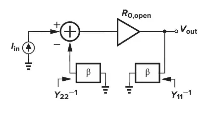
The following is a figure from 8.61 in Design of Analog CMOS Integrated Circuit, page 311:

enter image description here

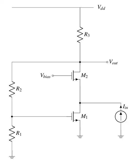
Here is the question: Calculate feedback \$\beta\$ of the following circuit:

enter image description here

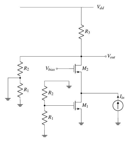
As we use the method of the book, we have to ground both of two terminal feedback network of the loop according to figure 8.61:

strong text

$$\beta = \frac{V_{out}} {I_{in}} = R_2 \parallel R_3$$

However, professor Ali Hajimiri on YouTube thinks the following:

$$H_{\infty} = \frac{1} {g_{m1}} (1 + \frac{R_2} {R_2})$$
ocrdu
  • 9,195
  • 22
  • 32
  • 42
kile
  • 798
  • 2
  • 11
  • Your feedback network is wrong. Where is the current summing point? – internet Mar 24 '24 at 14:58
  • @internet The feedback network is composed of $R_1$ and $R_2$ – kile Mar 24 '24 at 15:03
  • You should also include M1 in the feedback network. – internet Mar 24 '24 at 15:04
  • @internet I have never seen a feedback network with active component like transistor. The transistor are comprised of passive components for most of time.

    Can you draw correct feedback network in the answer section?

    – kile Mar 24 '24 at 15:06

1 Answers1

1

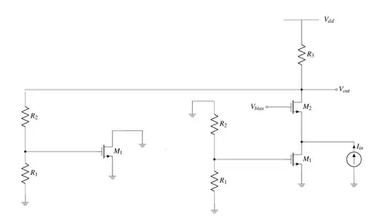
This is how I would break the loop for the voltage-current feedback.The feedback network includes R1, R2, and the transistor M1. enter image description here

internet
  • 544
  • 1
  • 3
  • 13