This is what you should have built (the relevant parts), according to the site you linked:
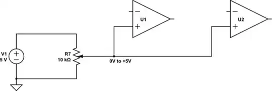
simulate this circuit – Schematic created using CircuitLab
This is what you actually built:
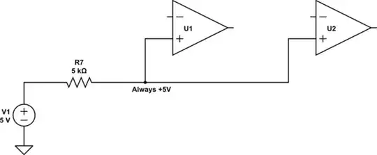
simulate this circuit
The non-inverting inputs are held at +5V, which means the outputs of U1 and U2 will be permanently high.
I believe this is what you intended to achieve:
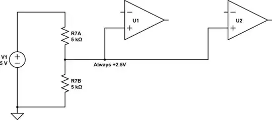
simulate this circuit
You failed to reproduce the potentiometer correctly. This potentiometer is effectively two resistors in series, whose total resistance (in this case) is always 10kΩ, and whose wiper is exactly half way along the resistive track. In other words, two 5kΩ resistors end to end, with the wiper at their junction.
That will produce +2.5V at that junction, or half the supply voltage.
Also, don't use a 5V supply with a 741 (or 747). This model of op-amp's output is severely constrained, and you'll need at least 9V (I recommend 12V) for this to work well.


