0

Ok here's a bullet list of what I'm working with

• 1 5v DC 2 wire reversible electric motor

• External 5v DC power source (battery pack)

• 2 12v small solar panels ( for signaling left or right rotation)

• 2 12v automotive dual switching relays

Ok I hope I can explain this properly and in enough detail.

What I want to do is control my 5v DC electric motor which has only two wires and is reversible by reversing the polarity. I have a 5V DC battery pack to power the motor.

And I have 2 small solar panels set accordingly behind my larger solar panels that are set up to be able to rotate left or right controlled by the electric motor.

I'll be using the smaller solar panels to act as my signal power to active the motor to spin in either direction. But I'm not sure on how to exactly wire this all up so that I do not short anything out.
toolic
  • 8,262
  • 7
  • 24
  • 35
  • Begin with your schematic circuit and follow it rigorously to ensure you don't make shorts. – Andy aka Mar 09 '24 at 12:31
  • @Andy aka I don't have schematics for this, that is why I am here. But thank you I will do that once I have schematics to follow – WizardDave Mar 09 '24 at 12:42
  • The added difficulty is in ensuring that the motor doesn't rotate to a direction that is 180 degrees opposite the sun (also a position where the two SPs produce the same signal). – Andy aka Mar 09 '24 at 12:53
  • Yes this is true and that is primarily controlled by precise positioning of the signal solar panels that I have fixed on the frame with solar panels so that they also rotate with them so that once the panels are inline with the sun the signal panels are in the shadow of the main panels and by using 12v automotive relays makes it require a great portion of my signal panels to be in direct sunlight to activate the relay. I have already tested this out for those perposes – WizardDave Mar 09 '24 at 13:10
  • This is important detail to add to your main question. You should not leave it as a comment. Maybe draw an image of what you mean. I'm not saying you are any more likely to get a decent answer but, without it you will likely get no answers. – Andy aka Mar 09 '24 at 13:15
  • I think you might be able to register for free to get the full article: Elektor solar tracker, if that's any help. – Andrew Morton Mar 20 '24 at 19:07

2 Answers2

0

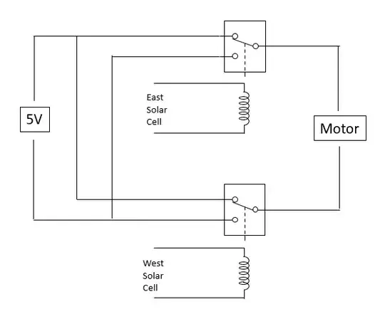
To do this right, you need some active circuits. Here is a passive circuit solution, but it has many issues.

You need a SPDT relay. Many automotive relays will be SPST.

At the end of the day the device will be pointing west. The next morning, neither guiding solar cell will have enough light to do anything.

Unless you live in the desert, clouds will be an issue.

enter image description here

Mattman944
  • 15,935
  • 1
  • 20
  • 47
0

Have a look at what this kit does: https://www.browndoggadgets.com/products/dual-axis-smart-solar-tracker

The tl; dr answer: you need finer control of the motor movement, which would be best accomplished using PWM controlling an H bridge. And, your setup needs to reset itself at the end of daylight.

hacktastical
  • 53,912
  • 2
  • 49
  • 152