4

Please refer to the following Verilog module:

module counter(
input  wire clk,
input  wire rstn
);

reg [4:0] counter;

// Powered by non-blocking assignments reg enable1; reg enable2; reg enable3;

// Powered by blocking assignments reg go_high_r1; reg go_low_r1;

// Powered by non-blocking assignments reg go_high_r2;
reg go_low_r2;

// Powered by continuous assignments wire go_high_3; wire go_low_3;

assign go_high_3 = (counter == 'd17); assign go_low_3 = (counter == 'd28);

always @ (posedge clk or negedge rstn) begin if (!rstn) begin counter <= 'd0; end else begin // let it overflow counter <= counter + 'd1; end end

// interaction b/w these signals below and enable1 signal is NOT clear always @ (posedge clk or negedge rstn) begin if (!rstn) begin go_high_r1 = 'd0; go_low_r1 = 'd0; end else begin go_high_r1 = (counter == 'd17); go_low_r1 = (counter == 'd28); end end

always @ (posedge clk or negedge rstn) begin
if (!rstn) begin go_high_r2 <= 'd0; go_low_r2 <= 'd0; end else begin go_high_r2 <= (counter == 'd16); go_low_r2 <= (counter == 'd27); end end

always @ (posedge clk or negedge rstn) begin if (!rstn) begin enable1 <= 'd0; enable2 <= 'd0; enable3 <= 'd0; end else begin enable1 <= (go_high_r1) ? 'd1 : (go_low_r1) ? 'd0 : enable1; enable2 <= (go_high_r2) ? 'd1 : (go_low_r2) ? 'd0 : enable2; enable3 <= (go_high_3) ? 'd1 : (go_low_3) ? 'd0 : enable3; end end

endmodule

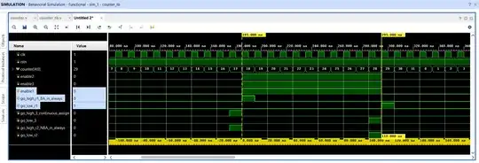
Waveform:

wave

I am able to understand the interaction between enable_2 and enable_3 and corresponding control signals.

What I am not able to understand is that how enable1 gets its value without a single clock cycle delay (source: ans1, ans2) from the point of time when either go_high_r1 or go_low_r1 gets its value from the procedural block.
lousycoder
  • 553
  • 3
  • 11

2 Answers2

3

The recommended Verilog coding practice is to always use non-blocking assignments to describe sequential logic. This means that assignments to signals inside an always procedural block which has a posegde clk (or similar) in the sensitivity list should use <=, not =. Doing so leads to predictable simulation results, both before and after synthesis.

If you don't follow this simple recommendation, you get results that are difficult to explain, and others who use your code will find it difficult to understand.

Try not to dwell too much on why it is this way. There are many discussions on the Verilog event queue out there to read up on, but sometimes that just gets in the way of designing what you want to design.

toolic
  • 8,262
  • 7
  • 24
  • 35
  • If I use always @ *, I think that can save me from this confusion. Is there any other way of creating a control signal without using NBA? In this case, the signal might be dependent upon a lot of factors, so I cannot use assign statement and I don't want to deal with the 1 cycle delay behavior of NBA (at least for control signals). If you'd like to share some of the discussions on the Verilog event queue, please do, as I suppose that these semantics remain same for SV too. – lousycoder Mar 09 '24 at 13:40
3

Although people tend to generalize by saying use nonblocking assignments for sequential logic and blocking assignments for combinational logic, the more precise rule is:

Use nonblocking assignments when one process writes to a variable, and another process reads the same variable, and both processes are synchronized to the same clock edge to prevent race conditions. This guarantees the reading process always uses the old value of the variable.

In your example it might be the ordering of the way you have written your 3 always blocks that determines whether the assignment to enable1 sees old or updated values of go_high_r1 and go_low_r1.

Synthesizable, combinational logic should always be written with blocking assignments. There are certain exceptions for modeling transport delays where you can use nonblocking assignments.

Within an edge triggered block, variables that are read before written within the same process will always become sequential logic regardless of which kind of assignment is used. Any variable written in one edge triggered process and read outside that process becomes sequential logic. That precise rule above still applies.

dave_59
  • 8,312
  • 1
  • 15
  • 27
  • Thank You Dave for the answer, based on your explanation, I think what is happening in the code is that it is written before it is read. The reason why I am thinking of using clocked procedural block instead of always @ * is that the former might result in a circuit having combinational delay distributed over a clock edge. – lousycoder Mar 09 '24 at 16:37
  • the read before write rules apply to within the same process. I've update my last paragraph. – dave_59 Mar 09 '24 at 17:29
  • Quoting: "Any variable written in one edge triggered process and read outside that process becomes sequential logic."

    I've corrected a mistake in the code of question details, Now referring to the signals in second always block from the top and enable1 signals.

    I'm able to digest the time at which 1go_high_r1 & go_low_r1 are "1". Not able to get is that how enable1 goes "1" without a clock cycle delay? As per quote, such a read becomes seq logic, which means that the value read from preceding FF cannot appear at the output of succeeding FF within a cycle, right?

    – lousycoder Mar 10 '24 at 12:52
  • 1
    That is the definition of a simulation race condition. A simulator will execute each always block serially, whereas synthesis and true hardware executes them concurrently. Changing the order of execution of a read versus a write process changes whether the now or old value is seen by the read process when using blocking assignments. – dave_59 Mar 10 '24 at 17:14
  • moral of the story: do not use blocking assignment in procedural blocks while writing synthesizable Verilog code. BTW, I recall your comment somewhere on the EESE where you said something similar to "it is expected from the synthesizer to produce a circuit which behaves exactly like the Verilog code responded in the simulation". – lousycoder Mar 10 '24 at 17:43