1

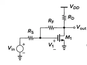
The following is from the book Design of Analog CMOS Integrated Circuit, page 319.

enter image description here

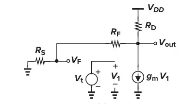
Let's break the loop at the gate of M1.

enter image description here

$$V_{out} = - V_T g_m \biggr[ (R_S + R_F) \parallel R_D\biggr] $$

$$V_F = V_{out} \frac{R_S} {R_F + R_S} $$

$$\Rightarrow \frac{V_F} {V_T} = - \frac{g_m R_S R_D} {R_D + R_S + R_F}$$

$$\Rightarrow L(s) = \frac{V_F} {V_T} = -\frac{g_m R_S R_D} {R_D + R_S + R_F}$$

\$\beta\$ negative since it's negative feedback.

$$V_G = \frac{V_{in} R_F + V_{out} R_S} {R_F + R_S} $$

$$\Rightarrow \beta = -\frac{R_S} {R_S + R_F}$$

$$A_{v, close} = \frac{L} {1 + L} \frac{1} {\beta} = \frac{g_m R_D (R_F + R_S)} {R_D + R_S + R_F - g_m R_D R_S} $$

However, the exact close loop gain is

$$A_{v,close} = \frac{(1 - g_m R_F) R_D} {R_D + R_F + R_S + R_D R_S g_m}$$

You can see how I derive this exact close loop gain from my previous post previous post.

the closed-loop frequency response of a feedback circuit can be expressed without reference to A(s)

$$A_{CL} = \frac{1} {\beta} \frac{L(s)} {1 + L(s)} $$

In conclusion, these two gains are not the same. Is there anything wrong here?
kile
  • 798
  • 2
  • 11
  • For a negatively feedbacked system, the voltage gain with feedback is given by: Av=A/(1+Aβ), where A is the voltage gain of the amplifier without feedback. – Franc Mar 06 '24 at 09:14
  • @Franc Can you explain the difference Gain with different method? – kile Mar 06 '24 at 10:01
  • Beta is wrong, this is an inverting amplifier, you have the term for a non-inverting one. – Designalog Mar 06 '24 at 10:29
  • In the book "Microelectronic circuits" by -Sedra-Smith-, on page 601, there is a BJT polarized in the same way, the study of the reaction should be very similar. However, it is an example found in many student texts. – Franc Mar 06 '24 at 10:30
  • @kile - you have two different expressions for the closed-loop gain. Both are wrong. The denominator in the 1st one must not show a minus sign - but for Rs=0 it gives the correct gain without negative feedback. And the 2nd one must not show a minus sign in the numerator. More than that, for Rs=0 it does not give the correct gain without feedback. – LvW Mar 06 '24 at 14:47
  • continued: With other words - the first one is correct if the minus sign in the denominator is replaced with a "+". – LvW Mar 06 '24 at 14:56
  • @LvW Why do you say the second one is incorrect? It's an exact solution if you can see my previous link on how I derive this 2nd equation. – kile Mar 07 '24 at 22:48
  • @kile - I wrote that the 2nd one would be incorrect because I thought that "beta" would be the feedback factor (as in most books and papers). However, when "beta" is the closed-loop gain (for very large open-loop gain) the gain expression is, of course, correct. This expression is a general one and applies for each amplifier with feedback and results from the definition of loop gain. That means, it can be used as a starting point for finding the specific gain of each real amplifier. – LvW Mar 08 '24 at 08:35
  • @Lvw There is no $\beta$ in my 2nd equation. My 2nd equation is $$A_{v,close} = \frac{(1 - g_m R_F) R_D} {R_D + R_F + R_S + R_D R_S g_m}$$ What's 2nd equation according to your definition? – kile Mar 08 '24 at 18:42
  • @kile - I agree my wording was a bit confusing. The 2nd equation for Av,close (with a "-" in the numerator) is not correct. More than that, the last equation (for ACL) is correct only in case the "beta" factor is the closed-loop gain (and NOT the feedback factor). However, this equation applies to each amplifier with feedback and is not specific for the circuit under discussion. – LvW Mar 09 '24 at 09:20
  • @LvW Is this your second equation?

    $$A_{v, close} = \frac{L} {1 + L} \frac{1} {\beta} = \frac{g_m R_D (R_F + R_S)} {R_D + R_S + R_F - g_m R_D R_S} $$

    – kile Mar 09 '24 at 10:45
  • @kile - No, I have mentioned the equation with a "-" sign in the NUMERATOR! With a "+" it would be correct. The equation as shown above (in your comment) is wrong. – LvW Mar 09 '24 at 12:25
  • @LvW Is this your 2nd equation? $$A_{v,close} = \frac{(1 - g_m R_F) R_D} {R_D + R_F + R_S + R_D R_S g_m}$$ – kile Mar 11 '24 at 12:59
  • @kile - yes, of course. – LvW Mar 11 '24 at 15:09

2 Answers2

3

When you write the formula in this format, you can easily see that \$ \frac{1}{\beta} \$ should be the ideal closed-loop gain when the loop gain approaches infinity.

$$\frac{1}{\beta} = \lim_{{L \to \infty}} \frac{1}{\beta} \cdot \frac{L(s)}{1 + L(s)}$$

When the loop gain approaches infinity, you can see that \$V_{GS}\$ should be 0, and from that, you can easily derive \$V_{out}/V_{in}\$ and \$\beta\$: $$ \frac{V_{\text{out}}}{V_{\text{in}}} = -\frac{R_{\text{F}}}{R_{\text{S}}} \quad \text{and} \quad \beta = -\frac{R_{\text{S}}}{R_{\text{F}}} $$

You may want to check Middlebrook's feedback theory lectures if you want to learn more about this.

internet
  • 544
  • 1
  • 3
  • 13
  • But you mentioned this equation before.

    $$V_G = \frac{V_{in} R_F + V_{out} R_S} {R_F + R_S} $$

    https://electronics.stackexchange.com/questions/701003/what-is-the-feedback-beta-for-this-resistor-feedback

    – kile Mar 06 '24 at 17:16
  • 1
    Yes, that is a simple result obtained by superposition. What you referred to as $\beta$ above is the ideal transfer function when the loop gain is infinity, not the feedback factor. – internet Mar 06 '24 at 17:35
  • "loop gain approaches infinity, you can see that $V_{GS}$ is 0" I don't know why you say $V_{GS}$ is 0. Can you explain in more details? – kile Mar 06 '24 at 17:45
  • 1
    Imagine the transistor as an op-amp. If the open-loop gain of the op-amp is infinite, the two inputs become virtually shorted. – internet Mar 06 '24 at 17:47
  • Do you mean Gate and Source of this transistor can be seen as two inputs of an op-amp? – kile Mar 06 '24 at 18:09
  • @kile No, but the gate and source are inputs to a transistor amplifier, so if the transistor's amplification is infinite, the inputs must be equal when the feedback is applied. It's not only op-amps that act that way. Any infinite gain stage with local negative feedback will behave exactly that way. Op-amps are just a particular case of a more general phenomenon. – Kuba hasn't forgotten Monica Mar 06 '24 at 18:19
  • @internet Is it possible to use 2-port network to analyse this circuit?

    If that's the case,

    I think $$g_{21} = \frac{V_F} {V_{out}} = \frac{R_S} {R_F + R_S}$$

    – kile Mar 07 '24 at 07:27
  • @internet - the problem is that you are using the quantity "beta" without sufficient definition/explanation. I think, normally and in most cases, such a symbol is used for the feedback factor. However, in your contribution it is the inverse of the closed loop gain for infinite loop gain. This should be clearly stated in order to avois misunderstandings. I think, the TO kile has used it as a feedback factor (in contrast to your definition). – LvW Mar 07 '24 at 10:15
1

@kile: I think, the loop gain calculation L(s) is correct.

However, can you please explain how you arrived at the term Av,close=[L/(1+L)]/beta ?

I rather think, that we always must use the form:

Av,close=af*Ao/(1+L) with loop gain L=Ao * beta and the forward damping factor af.

Added (edit): This forward damping factor (af) gives the input signal at the amplifiers input (gate) when there is no signal coming back from the amplifier output: af=(Rf+Rd)/(Rs+Rf+Rd)

LvW
  • 26,610
  • 3
  • 23
  • 56
  • It come from the book Analog Integrated Circuit Design by TONY CHAN CARUSONE (2nd version), Page 221 – kile Mar 06 '24 at 10:28
  • The formula is simply the closed-loop gain with an error term duebto finite loop gain. It's most likely part of most loop gain models; I know that part of the asymptotic gain model it is. – Designalog Mar 06 '24 at 10:32
  • However, I think his beta term is wrong. – Designalog Mar 06 '24 at 10:33
  • @Designalog What's $\beta$ according to you? – kile Mar 06 '24 at 10:41
  • @kile should be (-Rf/Rs)^-1 – Designalog Mar 06 '24 at 10:47
  • 1
    @Designalog $$\beta = -\frac{R_S} {R_F}$$? – kile Mar 06 '24 at 10:56
  • @kile - are you sure that the formula from the book can be applied here? For my opinion, it applies for unity feedback only (without any forward damping effect). More than that, your beta (-Rs/Rf) cannot be correct because this would mean: beta=-1 for Rs=Rf. – LvW Mar 06 '24 at 11:13
  • @LvW Designnalog said this. I am just reformat his comments in latex – kile Mar 06 '24 at 11:53
  • @kile yes, that's what I meant – Designalog Mar 06 '24 at 16:41
  • @Designalog How do derive this $\beta$? – kile Mar 07 '24 at 22:46
  • @Designalog Is $\beta = - \frac{R_S} {R_F}$ the feedback factor here? – kile Mar 07 '24 at 22:56
  • @kile - no, it is not. Unfortunately, Designanalog gas used this symbol for the ideal closed-loop gain (assuming that the open-loop gain would be infinite). This is the reason for some misunderstandings here. – LvW Mar 08 '24 at 08:29
  • @LvW I am very confused. What's the feedback factor here if it is not the feedback factor? – kile Mar 08 '24 at 18:37
  • @kile - read the 1st line of internet`s answer. Here you can read that "1/beta" is the ideal closed-loop gain. – LvW Mar 09 '24 at 09:23
  • ....continued: And the feedback factor is, of course: Rs/(Rs+Rf) – LvW Mar 09 '24 at 10:17