I have a homework and I need to simulate some circuits
I doubt very much that your homework expects you to drive 10A into the bases of small signal transistors.
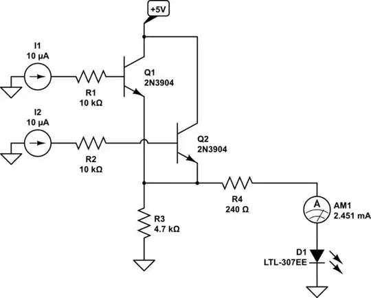
Here is a list of changes needed to get your circuit to work:
Current sources need to be referenced to some node. If no 2nd node is obvious, they must be referenced to ground (node 0 in SPICE parlance).
The supply voltage source must be referenced to ground.
The supply voltage of 1V is too low to do anything useful in this circuit. 5V is a good starting point.
The current sources should be driving a small current, perhaps microamps (suffix u in CircuitLab) or milliamps (suffix m in CircuitLab).
There are not all that many transistors that will survive having 10A driven into their bases for long. Note that the current sources don't care about resistors in their paths: if you tell a current source to drive 10A into a transistor through a 10kΩ base resistance, it will drive that current, developing 100kV across the resistor. The resistors used in such circuits will break down (turn into short circuits) with just a couple hundred volts applied across them. With 100kV, small parasitic capacitances of a long piece of wire for example will hold enough charge to vaporize the resistor and the transistor's silicon chip. Don't drive amps through kilo-ohms unless you're designing high-voltage circuits and the resistors are physically huge due to insulation lengths needed.
And... that's it. Make those changes and the circuit will do something useful like turn on the LED. To make it visible, add an amp meter into the circuit. CircuitLab performs DC analysis of simple circuits on-the-fly, so adding meter like ammeters and voltmeters will display the DC values immediately.
CircuitLab is built into this site, so that makes things even easier.

simulate this circuit – Schematic created using CircuitLab
In CircuitLab, you can save a bit of time by, instead of using a voltage source, using a net label that specifies the voltage on that node. E.g. in your circuit, the +5V supply can be provided as follows:
simulate this circuit
The syntax of supply voltage nodes is important: node name must start with either a + or a -, then a number with optional decimal point, then the V suffix. The sign, at least one digit, and the suffix must be always present. Additional digits, and decimal point, are optional.
i just want to know how do i configure it to know if the led is turning on or is not or to know how to interpret the plots.
What are you trying to plot? All you need to know is the DC LED current. It's just one number, nothing to plot.
Hover the mouse pointer over the LED to know what current flows through it. That's all, as long as the little green circle appears in the bottom-right of the simulator.
Or do as I have done and add necessary DC voltage and/or current meters to see what's going on without the need to hover mouse cursor over anything.
If that circle is yellow, the DC values won't be available instantly and you need to use the DC simulation to compute them. Then hover the mouse cursor that will turn into a little probe icon over one of the wires going to/from the LED, and read the current.
If the circle is red, there is a mistake in the circuit or component values or parameters, and no analysis is possible until the mistake is fixed.


