1

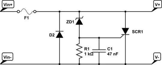
I am designing a device that will include a DC power jack. There is an external wall adapter that converts the 110-230 VAC from the mains to 20 VDC. Here is the schematic:

enter image description here

I intend to use a standard DC power jack, such as the 694106106102 from Wurth Elektronik (URL). The device will draw a maximum of 2 A from 20 VDC.

Here is my concern: I cannot prevent people from inserting an incompatible wall adapter. Thus, I need to make sure that this will not completely destroy the device. I suppose I need to prevent reverse polarity and over-voltage.

Do I need to add other protections? How are these protections generally integrated? Are there classical schematics/components that are usually used? Up to which voltage should I ensure over-voltage protection?

Thank you for your advice.

uz3il
  • 115
  • 5

2 Answers2

1

The simplest reverse connect circuit is a reverse biased diode connected across the input in series with a fuse.

To protect against a sustained over voltage rather than transients you can use a crow bar circuit. This is a SCR set up to be triggered in the event of the input voltage getting too high this again blows a fuse.

The fuse for these two schemes can be the same device. There are self healing or resetable fuses available.

schematic

simulate this circuit – Schematic created using CircuitLab

RoyC
  • 9,617
  • 6
  • 25
  • 42
  • This is my least favorite technique for this, partly because it relies on the very "soft" characteristics of a fuse. Also, D2 is way too small for a multi-amp environment. It might blow open before the fuse does, leaving the downstream circuit exposed to a large reverse voltage. – AnalogKid Mar 01 '24 at 13:40
  • Your right that diode is a bit small but is the default in circuit lab you need to select a diode for the expected fault current. Answer edited to address. – RoyC Mar 01 '24 at 13:47
  • @AnalogKid diode-fuse protection worked well for me saved a very expensive ham radio from reverse connection to a lead acid battery with hundreds of amps of short circuit current capability. – RoyC Mar 01 '24 at 13:55
0

I suppose I need to prevent reverse polarity and over-voltage.

and

Up to which voltage should I ensure over-voltage protection?

A wall adapter could produce 48 volts DC. There may be ones that produce more but, to put some kind of reasonable lid on the problem I would say 48 volts. As for reverse protection, a series diode of appropriate rating might be OK else, you should consider using a P-channel MOSFET wired to protect against reversals. This is a typical reverse protection circuit: -

enter image description here

Of course you can always use a parallel diode that blows a fuse or, blows a resettable fuse.

Do I need to add other protections?

You could consider using a TVS diode in case of ESD or line surges but, these are used less-often.

How are these protections generally integrated?

You don't tend to find an integrated solution for both reverse and over-voltage protection although I won't rule out that some are available.

Are there classical schematics/components that are usually used?

The reverse protection circuit is fairly well used. As for over-voltage, either you design to work up to the maximum or you add another regulator stage that can work up to the limit.

Andy aka
  • 456,226
  • 28
  • 367
  • 807