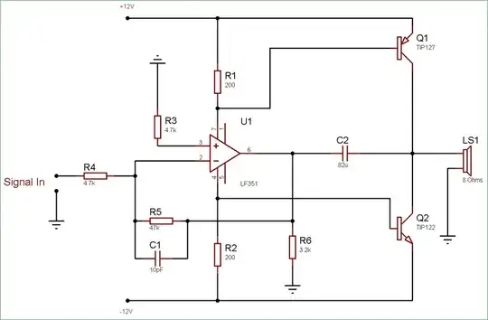
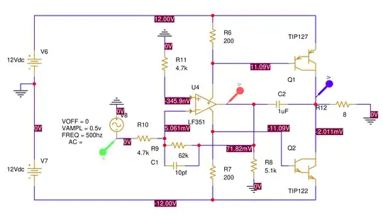
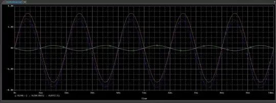
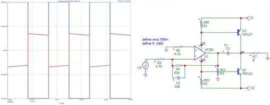
I am trying to simulate sound amplifier schematics that I found on the internet. R12 is used in place of an 8 ohms loudspeaker. For some reason it is not working as expected (please see graph below): top part of the sine wave is clipped, also there is DC offset in the output signal (violet graph). However, the sine curve at the op amp output (red graph) contains no distortion. My question is, why is it happening?
Asked
Active
Viewed 60 times
0
-
1I would not trust an op amp model to accurately reproduce the behavior of this sort of circuit. – John Doty Feb 28 '24 at 00:04
-
You should use, for testing, rectangular waves ... – Antonio51 Feb 28 '24 at 10:28
2 Answers
1
I raised value of C2 to 100uF and now the output sine has no distortion and Y-offset. Because the LF351 has a push-pull stage on its output it has to be properly AC-grounded to be able to drive the transistors. Hence, the capacitor.
Major Tom Workshop
- 21
- 1
-
It is highly likely that none of the op-amp models used in spice accurately reproduce the currents in the power supply leads. Circuits that do that stuff are fun and all, but are curiosities and not practical designs. There's zero need for this hackery. Just don't do it. Most sites that re-post these circuits have never taken care to actually assemble and characterize them. There are plenty of other current booster designs that don't care about op-amps nor their supply current - they use a discrete output stage driver and use the collector currents in it to control the boost. – Kuba hasn't forgotten Monica Feb 28 '24 at 17:37
0
However, the sine curve at the op amp output (red graph) contains no distortion. My question is, why is it happening?
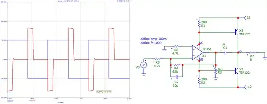
There is something that does not work in this circuit.
Tested with microcap v12
Response in TRansient Analysis (2 ampltudes input)
Antonio51
- 13,128
- 1
- 7
- 22
