4

I'm playing with UDN2981 source driver IC. But its inputs are so sensitive that the noise collected by connector wire switches them on. A simple touch is enough to set it on, but actually I don't want to make a touch sensor :)

I tried using pulldown resistors, but only under 1K worked successfully in all conditions, which is too small for pulldown, I think.

Are there other tricks to avoid false switching?

EDIT: added schematic alt text

It should display 3 alt text

csadam
  • 1,646
  • 2
  • 16
  • 24

4 Answers4

4

From a quick look at the two datasheets:

  • You should expect the 2981 to have very sensitive inputs - these are voltage driven logic inputs, which take a few hundred uA max to turn them on. They're expecting to be driven by a source which is confident about what voltage it's driving. If you disconnect them, you can expect them to wander around.

  • The segment outputs of the 7219 are current source outputs, which are expecting to supply current (mA) to the anode of an LED - instead you've connected them to a high-impedance input which basically draws no current at all.

I'm not really clear what the 2981 is bringing to the party here, but I guess you want more segment drive. If that's the case, you should convert the SEGx current outputs to voltage outputs, by arranging a pull-down resistor on each one. You will need to chose the current programming for the SEGx drives, and the resistor value, to give you sensible input voltages for the 2981.

  • cool. That completely explains why it is not stable without pulldown resistors. I have put pulldown resistors to segment outputs and it is not dimming now. But when I touch the inputs it dims again, I checked with scope and switches on with some noisy waveform, so... i will not touch it and should be ok :) – csadam Nov 21 '10 at 21:54
3

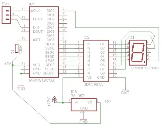
Change R1 to be 40-50kohm.

100kohm is way off the charts (literally its not even on the chart in the datasheet) for the device so i would venture a guess that the current limit is so low that they 7221 can't drive the inputs of the 2981 adequately causing the output voltage to drop to the point that its causing the malfunction.

You have a second problem as well. The DIG0 pin has to sink all the current from the common cathode. Are you sure your within the limits of the 7221's current sinking limits? Even more a problem, when the DIG0 isn't driving it doesn't tri-state but pulls to V+ which +5V vs the LED drivers +12V. In this one digit case that may be ok but it means that digit will never turn all the way off, you couldn't hook up a second digit like this. It also could mean that if DIG0 goes high and a segment is driven low, it will see a reverse 5V across the LED, i have no idea the reverse voltage specs on such a driver, but worth a safety check.

One interesting idea. When the LED drive is high (+12V) if the DIG0 line is released (+5V) your basically applying 12-LEDdrop to the +5V line on the 7221, that should result is fairly high current, as much as the LED will pass. It looks like the 7221 survives this, but if its current limit kicks in for all IO, this current may be triggering the rest of the chip into current limiting mode causing the SEG-IO pins to drop in voltage. Just a random guess tho, either way use a P-channel FET to control the common cathode to ground and see if that solves the problem.

Mark
  • 11,677
  • 1
  • 32
  • 38
  • I tried with 10K and 33K Iset resistors, but the result is the same. However I missed that the DIG line is not tristate, that could be the problem. I will try to control a ULN2803 sink driver with the DIG lines to make high current-high voltage switch for the leds. – csadam Nov 21 '10 at 19:36
  • or have the DIG0 output control a PMOS FET that switches the common cathode to ground. Just get a fet that is low voltage drop, is rated for your voltage/current and can be switched by +5V, should be easy to find. – Mark Nov 21 '10 at 19:40
  • I can see that this desing has too many errors :) There is no current limitation at all, the 7221 will burn if I add more digits in the current configuration. – csadam Nov 21 '10 at 22:01
0

Instead of pull down resistors you can try to use a capacitor to ground and a series resistor. Just remember to keep the time constant (R×C) lower than the speed of changing of the input. A factor of two to ten times lower could be enough.

The noise seems to be a kind of EMI noise, as you said that you're touching the wire and the lamp. Independente this case and pi filter could be a better alternative as it can reduce the noise from both sides of the circuit.

From wikipedia: [http://en.wikipedia.org/wiki/Capacitor-input_filter]

RMAAlmeida
  • 2,007
  • 16
  • 24
-3

Don't touch the inputs! Just wire them up and leave them alone.

Leon Heller
  • 38,983
  • 2
  • 62
  • 96