-1

I am designing a Colpitts oscillator.

I simulated the oscillator but there is no oscillation. I don't understand why.

Colpitts oscillator circuit:

enter image description here

I encountered a problem where once the component gets small enough (I want a frequency in the hundreds of MHz range), the oscillation stops. I would like a frequency in 433 MHz.

Can someone please explain why this happens and how I can fix this?

JRE
  • 71,321
  • 10
  • 107
  • 188
help_me_learn
  • 411
  • 1
  • 7
  • 135p is too low inductance. Increase it and lower the caps instead. – Michal Podmanický Feb 23 '24 at 15:37
  • Help_me, I started out wanting to say a few things... gave up. Instead, just decided to refer to the experts. This article from ARRL is a must-read for you, I think. They cover your frequency of choice, too. Transistor choices, full analysis, etc. All included. Do note that construction will be much of what's needed. Everything matters. – periblepsis Feb 23 '24 at 20:31

1 Answers1

0

I encountered a problem where once the component gets small enough (I want a frequency in the hundreds of MHz range), the oscillation stops. I would like a frequency in 433 MHz.

As frequency rises, the effect of the miller capacitor (a parasite inside every transistor between collector and base) becomes greater. This means that some topologies of Colpitts oscillators become harder to make work at higher frequencies. Yours is one of those.

Your circuit relies upon transistor gain and therefore the collector voltage is oscillating and this provides local negative feedback to the base and eventually, it prevents the circuit acting as an oscillator.

You should use the common collector type Colpitts oscillator as they don't rely on transistor voltage gain because the collector is held at a steady DC voltage. Meaning, there can be no negative feedback to the base via the miller capacitor: -

enter image description here

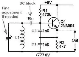
Image from my answer on a previous question about Colpitts oscillators

Here is an analysis of the common-collector Colpitts oscillator running open-loop

Andy aka
  • 456,226
  • 28
  • 367
  • 807
  • Andy, how does gain stabilization work? In every oscillator , the barkhausan criteria needs to be met where phase shift is 0 and loop gain is 1. But the loop gain needs to be slightly above 1 to start the oscillation right? How does a transistor common collector (gain of 1) or common emitter with degenerative resistor (the one i used) stabalize the gain? I haven't found information on this. thanks! – help_me_learn Feb 24 '24 at 15:25
  • @help_me_learn that's probably beyond the scope of the original question so please take note of What should I do when someone answers my question and I'll try and answer here. – Andy aka Feb 24 '24 at 16:35
  • I am going to make a new post. Thank you for the reminder. – help_me_learn Feb 24 '24 at 16:45
  • Well @help_me_learn if we are fully done here you should consider accepting my answer. – Andy aka Feb 24 '24 at 20:16
  • How are the resistor values chosen for the common collector circuit oscillator? – help_me_learn Feb 24 '24 at 20:23
  • I normally use two base bias resistors (as a potential divider) and an emitter resistor (as per the picture in my answer) of 470 ohm. I set the bias resistors to produce a voltage at the base that sets the emitter at approximately mid-rail between the supplies. Given a typical BJT beta of around 50 (at low UHF) this means the base resistors will be about the same value and about 50 times bigger than the 470 ohm i.e. two 22 kohm resistors would normally be about right. But, I always simulate first just to check because the design can be transistor dependent @help_me_learn – Andy aka Feb 24 '24 at 20:31
  • @help_me_learn are we done here? Do you know what to do when someone supplies an informative answer? – Andy aka Mar 02 '24 at 15:32