The datasheet doesn't seem to do much to help the designer does, it? The way these guys use just two pins to set LED current and provide a convenient voltage reference is clever, and flexible, but you have to decide how to exploit that yourself. You have a few approaches to choose from.
Do what they do on page 8
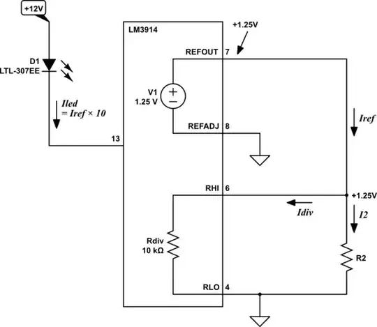
This is the same schematic as the one on page 8 of the datasheet, redrawn and annotated to make it easier to explain:
simulate this circuit – Schematic created using CircuitLab
Here they ground the low-potential side of the voltage reference (REFADJ), so that the high-potential end (REFOUT) is fixed at +1.25V.
That places fixed potentials of +1.25V and 0V at the two ends of the internal resistor divider (with a total resistance of 10kΩ), which will become the threshold levels at which LEDs will illuminate. If R2 were absent, the divider alone would draw:
$$ I_{REF} = I_{DIV} = \frac{1.25V}{10k\Omega} = 125\mu A $$
If R2 is present, then total reference current becomes:
$$
\begin{aligned}
I_{REF} &= I_{DIV} + I_2 \\ \\
&= 125\mu A + \frac{1.25V}{R_2} \\ \\
\end{aligned}
$$
We are told that LED current (in each individual LED, not total current) \$I_{LED}\$ is:
$$ I_{LED} = 10 \times I_{REF} $$
In this configuration, therefore, you can't have less than 1.25mA in each LED, but you can have more, by including R2.
Do what they do on page 9
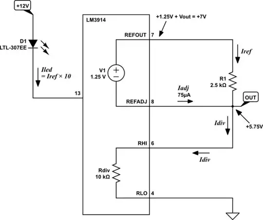
On page 9, the voltage across R1 is always 1.25V, and so it's trivial to control the current through R1:
simulate this circuit
By Ohm's law:
$$ I_{REF} = I_{R1} = \frac{V_{R1}}{R_1} = \frac{1.25V}{R_1} $$
The above relationship will be true regardless of what you connect to \$V_{OUT}\$ (within reason), and so R1 is so sole arbiter of that current. Again, LED current is ten times that:
$$
\begin{aligned}
I_{LED} &= 10 \times I_{REF} \\ \\
&= 10 \times \frac{1.25V}{R_1} \\ \\
&= \frac{12.5V}{R_1} \\ \\
R_1 &= \frac{12.5V}{I_{LED}}
\end{aligned}
$$
So, for example, if you require each LED (when lit) to pass \$I_{LED} = 5m A\$, then:
$$ R_1 = \frac{12.5V}{5mA} = 2.5k\Omega $$
It's still necessary to know \$I_{REF}\$, for later:
$$ I_{REF} = \frac{1.25V}{2.5k\Omega} = 500\mu A $$
We will also need \$I_{ADJ}\$, which is found in the datasheet:
$$ I_{ADJ} = 75\mu A $$
We are obliged to install R2, to sink both currents \$I_{REF}\$ and \$I_{ADJ}\$. Since \$I_{REF}\$ and \$I_{ADJ}\$ are both constant, whatever resistance R2 that you use will conveniently develop a steady "reference" potential \$V_{OUT}\$.
In my circuit above I've taken advantage of this, by using the IC's own internal resistor divider as R2. In other words, R2 is 10kΩ here. Consequently, the two currents \$I_{REF}\$ and \$I_{ADJ}\$ both pass through it, and \$V_{OUT}\$ becomes:
$$ V_{OUT} = (I_{REF} + I_{ADJ}) \times 10k\Omega = 5.75V $$
Do your own thing
Let's say you want 1mA LED current. That poses some problems for connecting the internal divider as R2, because that divider's resistance is prohibitively small, at 10kΩ.
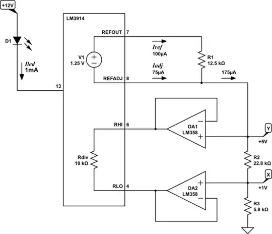
Nothing's stopping you from deriving your own low-impedance sources of top and bottom potentials for that divider, but you'll need to get creative. One way might be as follows (that's a bad pun, you'll get it in a moment):
simulate this circuit
Firstly, find R1:
$$ R_1 = \frac{12.5V}{I_{LED}} = \frac{12.5V}{1mA} = 12.5k\Omega $$
This will set \$I_{REF}\$ to one-tenth of LED current:
$$ I_{REF} = \frac{1.25V}{12.5k\Omega} = 100\mu A $$
I've chosen for the sum R2 + R3 to equal 28.6kΩ. By Ohm's law that makes \$V_Y\$:
$$ V_Y = (I_{REF} + I_{ADJ}) \times 28.6k\Omega = +5.0V $$
I'm still taking advantage of the internal reference to obtain this, avoiding the need for a separate reference IC. Then I divide that potential even further, using R2 and R3 to obtain +1V:
$$ V_X = V_Y\frac{5.8k\Omega}{5.8k\Omega+22.8k\Omega} = +1V $$
You can see why it might be difficult to employ the IC's internal 10kΩ chain in the place of R2 and/or R3 here, since its developed voltage would be too small. Also, I can't simply connect that internal divider directly to Y and X, so I use a couple of voltage followers to buffer those potentials, and take responsibility for divider current.
Now I have an LM3914 that will illuminate LEDs with 1mA each, in response to some input potential between +1V and +5V.