2

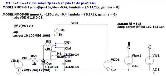
The first is the schematics from NMOS4 with parasitic capacitance:

enter image description here

From DC analysis:

--- MOSFET Transistors ---
    Name:          m3
    Model:       nmos-sh
    Id:          2.21e-04
    Vgs:         8.28e-01
    Vds:         8.42e-01
    Vbs:         0.00e+00
    Vth:         4.00e-01
    Vdsat:       4.28e-01
    Gm:          1.03e-03
    Gds:         2.03e-05
    Gmb:         3.08e-04
    Cbd:         2.32e-14
    Cbs:         3.32e-14
    Cgsov:       3.58e-15
    Cgdov:       3.58e-15
    Cgbov:       0.00e+00
    Cgs:         7.11e-14
    Cgd:         0.00e+00
    Cgb:         0.00e+00

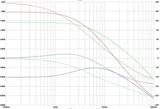
AC analysis:

enter image description here

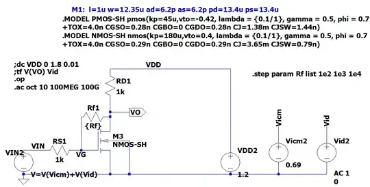
I tried to build an equivalent schematic with my .op analysis for the first schematic:

enter image description here

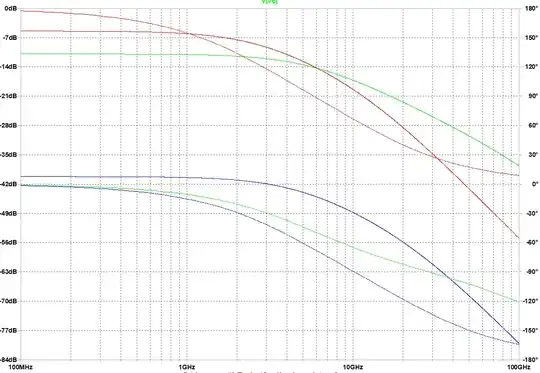
The following is the AC analysis:

enter image description here

You can see these two have significant differences in terms of AC frequency analysis.

What's wrong with my capacitor model?

The following is the asc file for whom is interested:

Version 4
SHEET 1 880 808
WIRE -224 16 -368 16
WIRE 32 16 -224 16
WIRE -368 32 -368 16
WIRE -368 160 -368 112
WIRE -304 160 -368 160
WIRE -368 176 -368 160
WIRE -368 176 -384 176
WIRE -368 208 -368 176
WIRE -304 256 -368 256
WIRE 192 256 192 208
WIRE 352 256 352 208
WIRE -608 288 -656 288
WIRE -576 288 -608 288
WIRE -464 288 -464 176
WIRE -464 288 -496 288
WIRE -416 288 -464 288
WIRE 32 288 32 16
WIRE -368 368 -368 304
WIRE -368 368 -656 368
WIRE -304 368 -304 256
WIRE -304 368 -368 368
WIRE 32 368 -304 368
WIRE 192 368 192 336
WIRE 192 368 32 368
WIRE 352 368 352 336
WIRE 352 368 192 368
WIRE -656 384 -656 368
FLAG -656 384 0
FLAG -224 16 VDD
FLAG -464 288 VG
FLAG -304 160 VO
IOPIN -304 160 Out
FLAG 192 208 Vicm
FLAG 352 208 Vid
FLAG -608 288 VIN
SYMBOL nmos4 -416 208 R0
WINDOW 3 56 60 Left 2
SYMATTR Value NMOS-SH
SYMATTR InstName M1
SYMATTR Value2 l=1u w=12.35u ad=6.2p as=6.2p pd=13.4u ps=13.4u
SYMBOL voltage 32 272 R0
WINDOW 123 0 0 Left 0
WINDOW 39 0 0 Left 0
SYMATTR InstName VDD2
SYMATTR Value 1.2
SYMBOL voltage 192 240 R0
WINDOW 123 0 0 Left 0
WINDOW 39 0 0 Left 0
SYMATTR InstName Vicm2
SYMATTR Value 0.69
SYMBOL voltage 352 240 R0
WINDOW 3 24 152 Left 2
WINDOW 123 24 124 Left 2
WINDOW 39 0 0 Left 0
SYMATTR Value 0
SYMATTR Value2 AC 1
SYMATTR InstName Vid2
SYMBOL bv -656 272 R0
WINDOW 0 -60 23 Left 2
SYMATTR InstName VIN2
SYMATTR Value V=V(Vicm)+V(Vid)
SYMBOL res -368 160 R90
WINDOW 0 0 56 VBottom 2
WINDOW 3 32 56 VTop 2
SYMATTR InstName Rf1
SYMATTR Value {Rf}
SYMBOL res -384 16 R0
SYMATTR InstName RD1
SYMATTR Value 1k
SYMBOL res -480 272 R90
WINDOW 0 0 56 VBottom 2
WINDOW 3 32 56 VTop 2
SYMATTR InstName RS1
SYMATTR Value 1k
TEXT -528 -152 Left 2 !.MODEL PMOS-SH pmos(kp=45u,vto=-0.42, lambda = {0.1/1}, gamma = 0.5, phi = 0.7\n+TOX=4.0n CGSO=0.28n CGBO=0 CGDO=0.28n CJ=1.38m CJSW=1.44n)
TEXT -528 -96 Left 2 !.MODEL NMOS-SH nmos(kp=180u,vto=0.4, lambda = {0.1/1}, gamma = 0.5, phi = 0.7\n+TOX=4.0n CGSO=0.29n CGBO=0 CGDO=0.29n CJ=3.65m CJSW=0.79n)
TEXT -496 -184 Left 2 ;M1:  l=1u w=12.35u ad=6.2p as=6.2p pd=13.4u ps=13.4u
TEXT -688 48 Left 2 !.op\n.ac oct 10 100MEG 100G
TEXT -688 24 Left 2 !;tf V(VO) Vid
TEXT 104 32 Left 2 !.step param Rf list 1e2 1e3 1e4
TEXT -688 0 Left 2 !;dc VDD 0 1.8 0.01
ocrdu
  • 9,195
  • 22
  • 32
  • 42
kile
  • 798
  • 2
  • 11

1 Answers1

5

I do not see \$C_{gdov}\$ in your model. This cap could be miller multiplied. This seems like a potential source of error in your modeling.

Btw, your open loop gain is 1 (!). The intrinsic gain of your mosfet is 50 but the \$g_{ds}\$ (\$=1/r_o)\$ is in parallel with \$R_{D1}\$,the open-loop gain at DC is then \$\frac{g_m}{g_{ds}+1/R_{D1}}\$, which, given your small signal parameters, come out as 1. In other words, your mosfet doesn't have any open-loop gain to sustain a proper negative feedback operation.

I suggest you increase the impedance of your feedback network such that the loading is negligible compared to your \$R_{D1}\$ resistor. Or better yet, use a proper current source.

Just as an FYI, the output of this amplifier is given by (assuming your loop gain is large): $$ V_{out} = V_{gs}\left(1+\frac{R_{f1}}{R_{s1}}\right) + V_{in}\left(-\frac{R_{f1}}{R_{s1}}\right) $$

Designalog
  • 3,990
  • 1
  • 14
  • 25
  • Should I add $C_{gdov}$ to $C_{gd}$ becuase they are in parallel? – kile Feb 11 '24 at 00:05
  • @kile I'd say so – Designalog Feb 11 '24 at 00:06
  • That would be an easy fix – kile Feb 11 '24 at 00:06
  • what is the value of $R_f$ when DC gain is 50? Many said it was not a feedback circuit. When do break up the circuit in order to have open loop? Could you show a piciture where you break up the circuit and add test voltage? – kile Feb 11 '24 at 00:08
  • This is an inverting amplifier, so based on your input resistor it should be 50k for a -50 gain. But this 50 gain I mentioned is the open loop (gm/gds). – Designalog Feb 11 '24 at 00:10
  • @kile very late over here, but you can add a voltage source between VG and the gate of your transistor. Loop gain is the voltage ratio between both voltage source terminals – Designalog Feb 11 '24 at 00:12
  • Sure. Do it whenever you have time. Can you tell me a little more on how you get open loop gain is $\frac{g_m} {g_{ds}} $? – kile Feb 11 '24 at 00:12
  • @kile I think he was talking about the intrinsic gain of the MOSFET, $g_m r_o$. – internet Feb 11 '24 at 06:42
  • @kile it's the intrinsic gain of the mosfet, but it wasn't relevant for your circuit, as the $r_o$ is in parallel with $R_{D1}$. I edited my answer. – Designalog Feb 11 '24 at 07:24
  • @Designalog feedback loop is $\frac{A} { 1 + A \beta} $. In this case, A is 1. so it will be $\frac{1} {1+ \beta} $. But I don't know you get $\mbox{$\Large V_{out} = V_{gs} (1 + \frac{R_{f1}} {R_{s1}}) - V_{in} \frac{R_{f1}} {R_{s1}} $} $ – kile Feb 11 '24 at 08:12
  • @kile the formula you've written is the transfer function for a simplified feedback system. The whole point of feedback is that A is so large that $\frac{A}{1+A\beta}\approx\frac{1}{\beta}$. This transfer function is assuming you have one input, but, in fact, you have 3 DC inputs to your amplifier with respect to the output, namely, your intended input, the gate voltage and the supply. The above transfer function is only about the 1st 2. The supply transfer towards the output is usually specified as PSRR. – Designalog Feb 11 '24 at 08:29
  • By the way, your question seems to have morphed into another one. Did you already manage to correct your transfer function with the addition of $C_{gdov}$? – Designalog Feb 11 '24 at 08:32
  • Remember the typical textbook $V_{be}$-multiplier circuit? This is pretty much the same, except that you're also using the input resistor to the gate. – Designalog Feb 11 '24 at 08:34
  • @Designalog What's the $\beta$ here? How can I calculate it? What do you mean " 3 DC inputs to your amplifier"? – kile Feb 11 '24 at 08:52
  • @kile I'm willing to put some work on to answer that, but ask it in a different question. Your original question was about the discrepancies in both of your models. – Designalog Feb 11 '24 at 09:08
  • 1
    @Designalog Take a look at my new post. https://electronics.stackexchange.com/questions/701003/what-is-the-feedback-beta-for-this-resistor-feedback – kile Feb 11 '24 at 09:25