0

The robot I'm working on has some some components rate either 360 V or 370 V max (no explicit never exceed values), with nominal voltages of 320 V.

The robot is powered through a very long cable (with not enough copper section to my taste, but there is no alternative for now), so we need to supply the robot with voltages a bit higher than nominal the higher the better (so we still get acceptable voltages at high loads).

Going close to the limits, I would like to add solid over-voltage protection at the robot end of the cable.

Ideally, I would like:

  1. To clamp short over-voltage spikes. After the clamp, the voltage should never exceed 359 V. The maximal working voltage should be as high as possible.
  2. For prolonged (or repeated) over-voltage, somehow cut off power (blow a fuse, open a relay or a MOSFET, ...).

There is no precise requirements what duration qualifies as transient, and when it starts being a prolonged over-voltage, the important thing is that the voltage never exceeds 359 V.

The current can be up to 35 A.

A simple solution would be a fuse followed by a TVS diode:

schematic

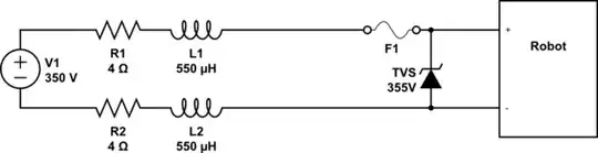
simulate this circuit – Schematic created using CircuitLab

(R1, R2, L1, L2 represent typical cable resistance/inductance, but can vary by a factor 2 depending on the cable length used)

However, as far as I know, TSV diodes are very imprecise, so don't match well the requirement to a rather precise over-voltage threshold.

Do you have an idea how to achieve such precise over-voltage protection (suppressing short transients, and cutting supply (blowing fuse?) for prolonged over-voltage)?

Cost doesn't matter (the equipment to be protected is likely to be at least 2 orders of magnitude more expensive than the components needed). Compactness is a plus.

EDIT :

to get an order of magnitude for the transients, I did some simulations (nb : I decreased C1 by 2 orders of magnitude, otherwise, there is no overshoot at all)

schematic

simulate this circuit

overshoot

So I think that a 600V spike for 300µs should be a good approximation of worst case. I would therefore aim for protecting against 1kV for at least 2ms without blowing a fuse.

Sandro
  • 7,277
  • 11
  • 37
  • What causes the spikes or, what are their transient characteristics. – Andy aka Feb 05 '24 at 12:45
  • For the transients/spikes, there should be some when brutally stopping the motors (inductive cable, brutal reduction in current (potentially from 35A to 0.05A). Maybe some from the surface supply, or picked up noise. Theoretically lightening hitting water nearby (but I'm not really designing for this scenario). Measuring transients however is very complicated (in air, the current drawn is 3A max, in water I ca no longer connect a scope). In addition, the exact cable used changes a lot (length, and sometimes even type), with exact length that might start to mater (transmission line effects) – Sandro Feb 05 '24 at 13:00
  • So measuring "all possible transients" is far more expensive than just over sizing the components – Sandro Feb 05 '24 at 13:01
  • You can't over-size something without knowing what the size is to begin with. So, either you take a guess (and live with the repercussions if you are wrong) or, measure something. – Andy aka Feb 05 '24 at 13:25
  • "I decreased C1 by 2 orders of magnitude, otherwise, there is no overshoot at all" -- Why would this not be a viable method of suppression? It works just fine for many devices! If you could explain what your drives/PSUs/other loads are made of, abs max ratings, etc., that would help justify the tight requirement. – Tim Williams Feb 05 '24 at 15:00
  • What I mean is that I decreased it in the simulation, not in real life. For in air tests, the capacitance is enough to avoid any overshoot. I haven't done any in-water testing yet (I just found a way to do them, but it will be a few days before the equipment is ready). I suspect however that there are still transients over-voltages in some cases, even if I wasn't able yet to reproduce them (it's the easiest explanations for some faults I observed) – Sandro Feb 05 '24 at 15:28
  • @TimWilliams PSU is a high power lab supply: at 320V it seems to work quite well, but the voltage is a bit too low at high load, at 350V we get more mechanical power, but observed a higher failure rate (most failures could be explained by transients, even if I have no proof it's the cause). The load is 6 motors (320V nominal, 360V max) and a DC/DC converters. I need higher than nominal voltage to compensate for voltage drop in the cable at high load (therefore, at low load I'm very near the maximum):the safety margin is therefore reduced, leaving only a small margin between normal and clamping – Sandro Feb 05 '24 at 15:41
  • Right, I gathered that. What about the motors, the converters, which ones fail, are they forever a mystery to us, do we not get to peek inside? Are they a variable under design control, is changing/modifying them an option? If none of these, it sounds like the correct engineering decision is to settle with the reduced maximum power. – Tim Williams Feb 05 '24 at 15:47
  • We had several motors failing (either not working or insulation resistance going bellow 20Mohms). We had a DC/DC destroyed after a significant overvoltage (human error, but this circuit could have prevented damage), and at least one PCB that got destroyed because of an over-voltage on it's 12V rail (coming from the DC/DC), which I suspect to be the DC/DC not rejecting well enough an input transient above it's maximum. Both motors and DC/DC are of the shelve components, and will not be replaced anytime soon (it's planed long term, but we need a solution in between) – Sandro Feb 05 '24 at 15:55

0 Answers0