0

Wikipedia gives the following circuit as a negative capacitance circuit:

enter image description here

I was curious if I would be able to create a low-pass resistor-negative-capacitance filter, analogous to an RC low-pass filter, using the above circuit, which would have a positive phase shift above the cutoff frequency.

This is what I tried:

schematic

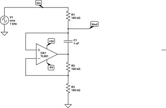
simulate this circuit – Schematic created using CircuitLab

Running a frequency response simulation showed promising results:

enter image description here

enter image description here

Obviously, at a certain point, the op-amp's performance begins to flag, so I am not surprised that the phase shift continues to rise above 90° when the frequency is above 1 MHz.

However, I was very disappointed to see the time-domain response. My low-pass filter unfortunately is also a relaxation oscillator. Typically, an op-amp relaxation oscillator has the capacitor connected between the inverting input and ground, but obviously this topology works as a relaxation oscillator as well.

enter image description here

My questions are:

  1. Is there a (not too complicated) way to suppress the relaxation oscillations, or is this negative capacitance circuit useless for making an R/"C" low-pass filter?

  2. Is there an alternative way to make a low pass filter with a positive (90°) phase shift in the region where there is 20 dB / decade attenuation?

This question is related, but unfortunately, the OP only did a frequency response, and didn't understand why the circuit did not work in practice. A scope or a time domain simulation would have shown the relaxation oscillations.

ocrdu
  • 9,195
  • 22
  • 32
  • 42
Math Keeps Me Busy
  • 23,260
  • 4
  • 21
  • 75
  • 1) the arrangement itself is a relaxation oscillator having an oscillation frequency of $f\approx1/(2\ln(3) \ RC)$ where R is 100k (there are 3) and C is 1n. Without any input the circuit should oscillate. Maybe you can start with different resistance values (just to disturb the R ratio). 2) Did you consider negative resistance instead? – Rohat Kılıç Jan 23 '24 at 16:28

1 Answers1

0

Your circuit is not a lowpass filter. Why not? Because you must not trust a small-signal simulation in the frequency domain only!

In the case under discussion the rising phase and - at the same time - the falling amplitude (gain magnitude) are a clear indication of instability.

Note that such an ac analysis (small-signal analysis in the frequency domain) assumes:

1.) That the power supplies are ideal (constant) and available without any switching transients.

2.) That there are absolutely no external influences (noise an/or other fluctuations).

3.) Mechanical analogy: Under such ideal conditions even a small ball could be positioned on the top of a larger ball.

4.) As a consequence, each ac analysis gives correct and realistice results only for stable systems

5.) Even a visual inspection of your circuit reveals that for frequencies above a certain frequency limit the positive feedback will govern over the negative feedback.

LvW
  • 26,610
  • 3
  • 23
  • 56