1

I have the following voltage regulator circuit (AMS1117 SOT-223):

schematic

simulate this circuit – Schematic created using CircuitLab

C1 is ceramic and C2 is tantalum. The 3.3V output is used to power a microcontroller.

When input is 5V, everything works fine. However, when I use 12V on input, the regulator burns immediately (and the microcontroller gets destroyed too).

When I begin with 5V and gradually increase it to 12V, it survives and works fine.

I guess that the problem is that when I connect the input voltage, the C2 is being charged by too high current that destroys the AMS1117.

What can be done to prevent this issue? I never thought about output capacitor having too high capacity or too low ESR. How to properly select it? Or is the problem somewhere else?

I replicated this behavior with multiple AMS1117, but when using TS1117 it does not occur.
winny
  • 14,707
  • 6
  • 46
  • 66
Jiří Maier
  • 1,294
  • 3
  • 17
  • Strange. The AMS1117 should internally limit itself and many designs have large output capacitors with inrush to deal with for the regulator, so your case isn't unique. What's the ESR of the input and output capacitor? – winny Jan 15 '24 at 07:53
  • 3
    Is it possible that you have fake AMS1117? – Jeroen3 Jan 15 '24 at 07:58
  • I don't think your problem is the output capacitance. The datasheet specifically recommends at least 22uF (or even higher) output capacitances for stability and faster transient response. My first intuition was that you have somewhat broken or a fake chip. – Rohat Kılıç Jan 15 '24 at 07:59
  • C2 sais1.7Ω@100kHz, I couldn't find the value for C1, type is CL21A226MAQNNNE – Jiří Maier Jan 15 '24 at 08:01
  • It is from JLC PCB assembly service, Is it possible that they have fake chips? – Jiří Maier Jan 15 '24 at 08:02
  • 2
    Unless purchased from well-known retailers (e.g. Digikey, Mouser, etc), I personally wouldn't trust any of them. Apart from I came across a few fake op-amps, there's one I can never forget: Years ago we were trying to find an equivalent of an obsolete chip, a far-eastern kinda well-known "manufacturer" offered us an equivalent, they also offered to print the obsolete chip's details if needed. Anyway... If possible, try to increase the input voltage gradually to see if it still gets fried or at what voltage it fails. – Rohat Kılıç Jan 15 '24 at 08:07
  • When increasing gradually, at 15V the C2 exploded (it is 6.3V, so the 12V must have got to output at that point). 15V input is the maximum input of AMS1117 by datasheet. – Jiří Maier Jan 15 '24 at 08:25
  • 1
    Have you measured the output during the gradual increase? Was it 3.3V or was it increasing as you increase the input? – Rohat Kılıç Jan 15 '24 at 08:28
  • 2
    Double check so the tantalum isn't mounted backwards. They like to explode if mounted backwards and given enough power. – Lundin Jan 15 '24 at 08:43
  • 3.3V until the explosion happened (but I don't know what exactly happened immediately before it exploded; I only checked by multimeter, not by scope) – Jiří Maier Jan 15 '24 at 08:44
  • It is not backwards. I think that the input voltage got to output when the AMS1117 failed. And that exceeds the capacitors maximum voltage 2-times. With 12V it didn't explode, but the microcontroller got destroyed. – Jiří Maier Jan 15 '24 at 08:46
  • Have you also replaced the 1117 after the failure? Can you measure resistance between input and output when the circuit is not powered? – Rohat Kılıç Jan 15 '24 at 08:51
  • Then it does sound as if you got "Aliexpress" parts instead of working ones. And it seems that these parts don't have a great reputation even when working as intended. I think LM1117 might be pin and function compatible? Maybe buy a few of those from ON Semi or Texas, see if they solve the problem. – Lundin Jan 15 '24 at 08:52
  • I can't measure resistance between input and output because I already destroyed all I had. I tried replacing it, but the circuit won't work as other components are damaged too (The destroyed microcontroller is shorting 3.3V to GND). When I desoldered all other chips and tried again, it behaved the same (fails when 12V is connected) – Jiří Maier Jan 15 '24 at 08:59
  • 1
    JLC PCB are as reputable as you can get from China. Not to say they MAY not be fakes, but unlikely. AMS1117 from some suppliers has Vinmax of about 12V (I'm told). || Try adding a series input resistor of R = V/I = (Vin-5V)/Imax. eg for 250 mA max and Vin = 12v, R = (12-5)/0.25 = 28 Ohms. Use eg 27 Ohms. This drops most of the in across the resistor. || Resistor power = I^2.R = 0.25^2 x 28 =~ = 1.7% W --> Use 5 Watt. – Russell McMahon Jan 15 '24 at 10:07
  • 1
    The regulator might be oscillating (although I wouldn't really expect it to burn in that case). Can you check what happens on the output pin with an oscilloscope? – marcelm Jan 15 '24 at 13:48
  • 1
    "but the microcontroller got destroyed" To cover the basics: What is the actual maximum current draw through this regulator? Have you run the power dissipation calculations, (at dV of 8.7V) considering Rja (C/W)? What is the thermal management on your board/IC? A pic of the PCB may help us help you. – Chris Knudsen Jan 15 '24 at 14:56
  • I wouldn't trust an AMS1117 in general. The LM1117 is usually more stable. – Hearth Jan 16 '24 at 01:34
  • 1
    WARNING The "bar" on tantalum capacitors is often POSITIVE and not negative as usually expected. , || Use of tantalum capacitors is usually a very bad idea UNLESS you have a very specific need for one AND you understand fully what you are doing. Modern ceramic capacitors are usually a better proposition. – Russell McMahon Jan 16 '24 at 09:54
  • Tantalum fun: See https://electronics.stackexchange.com/a/99321/3288 || I can think of no obvious reason to nowdays ever use a tantalum capacitor. And few in the past. || I've seen one that gave a bad smell, then a loud shrieking noise, then a jet of flame with gratifying wooshing sound then an impressive explosion. – Russell McMahon Jan 16 '24 at 09:55

2 Answers2

2

The datasheet of the regulator vaguely claims that it has short circuit protection and current limiting without elaborating much further. Also, the datasheet states:

If high value output capacitors are used, such as 1000µF to 5000µF and the input pin is instantaneously shorted to ground, damage can occur.

I'd test the IC by short circuiting the output to see if it actually does what the datasheet claims. Just because it claims something, it doesn't necessarily 100% means it's true.

I'd suggest you use a regulator from a reputable manufacturer, like TI, Infineon, Microchip, NXP, STMicro, Analog devices, Diodes inc.

Otherwise, you could add a dedicated current regulator for soft start. But this is something that a good regulator should already have built in.

DELTA12
  • 878
  • 6
  • 18
  • AMS117 over current / over temperature protection is mostly theoretical... this regulator is just terrible. LDL1117 from ST is a good substitute with same pinout, higher performance, much lower idle current, and it actually works. – bobflux Jan 16 '24 at 01:04
2

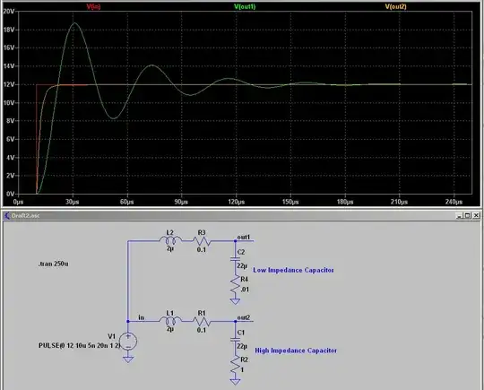
A possible failure mode may be caused by ringing creating an over voltage condition on the regulator input.
Depending on the input wiring, the input voltage can exceed the maximum ratings of the voltage regulator due to the line inductance and having a low-impedance input capacitor.

An example is shown below with a low ESR (Equivalent Series Resistance) capacitor (10m ohms series resistance) and a high ESR capacitor (1.0 ohm series resistance). The inductance of the wiring between the power source and the input capacitor can causing ringing if the voltage is suddenly applied. The trick is to minimize the wiring inductance by twisting the wires together, use short leads between the power source and input capacitor, and use a high ESR capacitor on the input (small aluminum electrolytic capacitors can have a few tenths ohms ESR) instead of a low ESR ceramic capacitor.

I mention this case since you stated that if you ramped the voltage from 5 V to 12 V, you didn't have problems. You may want to monitor the input voltage at the input capacitor and see if you have this ringing problem.

enter image description here

qrk
  • 9,494
  • 1
  • 7
  • 26