Can somebody explain in a more mathematically way when and how a transistor enters its saturation mode, that's for example the case in a constant current source. I understand the consequences but not why the transistor goes into this mode. As I understand this saturation mode the transistor is able to vary the emitter-collector voltage with its base current, but the base current does not change the base-emitter voltage.
Asked
Active
Viewed 102 times
1
-
1What level of mathematics would you find a suitable explanation for the phenomenon? Also which transistor, BJT or FET? – Tim Williams Jan 11 '24 at 14:41
-
Have you reviewed these questions, and have they proven informative, or, what are your remaining concerns? https://electronics.stackexchange.com/questions/689967/operating-regions-of-bjt https://electronics.stackexchange.com/questions/670229/how-would-the-collector-current-be-affected-during-saturation-mode-in-a-npn-tran https://electronics.stackexchange.com/questions/674939/can-collector-current-change-when-transistor-is-saturated – Tim Williams Jan 11 '24 at 14:43
-
1I can't make sense of the question. Saturation mode is not what a BJT is in when it's a constant-current source. – John Doty Jan 11 '24 at 15:43
-
1@JohnDoty it's always annoyed me that what is called saturation for a bipolar, and a FET, are opposite things. I wonder if the OP is asking about bipolar, while thinking FET? – Neil_UK Jan 11 '24 at 16:07
-
1@Neil_UK Or being confused by the saturation current parameter in the Ebers-Moll equation. The word is severely overloaded. – John Doty Jan 11 '24 at 16:10
2 Answers
2
If you are looking for a bright line answer, then the following diagram provides it:

Saturation is anywhere on the left. Active mode is anywhere on the right of the bright yellow line.
In this viewpoint, whenever the BC junction is in any way forward-biased, the bipolar transistor has crossed the line.
Reality is a little more nuanced, as saturation is kind of soft at first. When the BC junction is only slightly forward-biased, it can be largely ignored and the bipolar transistor appears to work as if it were in active mode. You can see this also in the above picture, as the green line shows the \$\beta\$ being quite similar to the active mode \$\beta\$ with only a very gradual decline until the BC junction is forward-biased by \$\ge 450\:\text{mV}\$ and the green line traces out a much more rapid decline in \$\beta\$.
When the BC junction is forward-biased by \$\ge 450\:\text{mV}\$, the collector has, by definition, been pulled about as close to the emitter as possible and the collector starts to look much more like a voltage source and a lot less like a current source.
Some defer the meaning of saturation until this point is reached, rather than saying saturation happens when the BC junction is forward-biased by any amount at all.
It's really just a matter of application space, though. For switch use, this latter "BC junction is forward-biased by \$\ge 450\:\text{mV}\$" definition is better because the goal in switching is to have the collector very close to the emitter and acting like a voltage source. For voltage amplifier use, the "BC junction is forward-biased by \$\ge 0\:\text{mV}\$" definition is better because it is very important to have the collector acting like a current source and to avoid getting into a situation where deeper saturation and switch-like behavior increasingly occurs.
periblepsis
- 8,575
- 1
- 4
- 18
-
Can't recall if I've seen anyone use a common-base definition of saturation, at least in books newer than the 1960s. But I suppose it's as arbitrary as anything else. – Tim Williams Jan 11 '24 at 14:35
-
@TimWilliams I was trying to quickly provide something that a beginner could latch onto, without losing sight of the larger picture as well. Often, when just starting out, one looks for bright lines. That's because the nuances are far in their future and they need something to chew on, now. This was the best I could pony up quickly. – periblepsis Jan 11 '24 at 14:37
-
Yeah, I see that. Hmm, the question asks "mathematical way", but doesn't give any hint what degree of mathematics would be satisfactory here. Better to assume minimal, then (a graphical or geometric explanation, say)? – Tim Williams Jan 11 '24 at 14:41
-
@TimWilliams The only mathematical definition possible is to say Vbc >= 0, if to have any hope of removing all manner of more subjective choices. Every choice is subjective to some degree. But I think Vbc > 0 (or Vbc >= 0) are perhaps the closest possible towards objective as one may be able to get. And it is certainly the more mathematical without perhaps getting into microelectronics and perhaps some other definitions based on finer details there that are hidden or very obscure at the simpler BJT model level. So again, best I could do to address the mathematical part of the question. – periblepsis Jan 11 '24 at 14:44
-
[If you'll entertain further philosophy--] I wouldn't say only; there is a cluster of important parameters that all change notably in the general region, and how much varies from device to device; and can include values outside the region indicated. We quickly get into a "Behold, a man" conundrum if we go so narrow. As is so often the case in mathematics, I would say what's most valuable is its relationships, when an object can be defined in many equivalent, ways (in this case, not necessarily equivalent due to device properties). – Tim Williams Jan 11 '24 at 14:53
-
@TimWilliams This conversation demonstrates the difficulties in providing a singular answer to someone asking for one. – periblepsis Jan 11 '24 at 15:15
1
Plain answer
My explanation is not mathematical, but I believe it will be very useful to you because before you can calculate a circuit, you have to understand it intuitively.
Think of the transistor as a variable resistor ("rheostat") that adjusts the current in the voltage-supplied circuit by changing its resistance. In order to obtain a varying voltage, we connect a resistor Rc in series to the collector and take the voltage Vce (Vc) between the collector and the emitter as the output.
As the input voltage increases, the transistor begins to decrease its "resistance" and the current increases. The voltage drop across the collector resistor increases and across the transistor (output voltage) decreases. The transistor is capable of changing the current or, as they say, it is in "active mode".
Eventually, the transistor exhausts its supply of "resistance" and cannot reduce it below zero (only negative resistors can do this magic but the transistor is a "positive resistor"). As they say, the transistor has "saturated".
Here are some quantitative considerations ("math"). The transistor will be saturated when the voltage Vce becomes almost zero, and this will happen when the voltage drop VRc across the collector resistor becomes equal to the supply voltage - VRc = Ic.Rc = Vcc (ie, when all the voltage is lost across the collector resistor and there is nothing left for the transistor.
This will happen when the base current is greater than Ic/β. In the simplest case, the base current is determined by an input voltage Vin and a base resistor Rb, so Ib = Vin/Rb. So β.Rc.Vin/Rb = Vcc is the saturation condition of the transistor.
CircuitLab experiments
Presented in this way, "saturation" is a concept that is not only related to BJT but is much more general. To demonstrate this, I have used three different levels to perform the same CircuitLab experiments - with a variable resistor, a current source and finally a transistor.
Conceptual resistor circuit
Current output: To control the current, let's connect a variable resistor Rce (rheostat) in series to the voltage source. The ammeter Ic serves as a current load. So, when Rc varies...
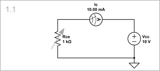
simulate this circuit – Schematic created using CircuitLab
... the voltage across it is constant...

... and only the current varies. The curve is non-linear because the resistance is in the denominator of the Ohm's law expression Ic = Vcc/Rce.

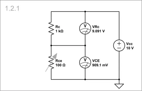
Voltage output: To get an output voltage, we can insert a resistor Rc in the collector. A "floating" voltage drop VRc occurs across it, but we prefer to take its grounded complement Vce across the transistor.
"Active mode": When we change Rce within certain "reasonable" limits without reaching the final values (zero and infinity), the resistor Rce is "active" (it can change the current and voltage).
For example, if we change (sweep) Rce from 100 Ω to 1 kΩ, VRc decreases from 9 V to 5 V, and Vce increases from 1 V to 5 V.

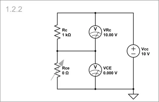
"Saturation": When Rc = 0 Ω, Vce = 0 V and cannot decrease further.
We can see this Rce "saturation" in the beginning of the Vce curve.

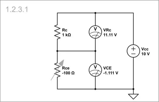
Negative resistance: For Vce to continue decreasing, Rce must become negative. And here, as a joke, I set Rce = -100 Ω... and it worked! Very interesting, the simulator could work with negative resistances!
Now the Vce curve begins from below zero (-1 V), and at 0 V the transistor is not saturated.

Hmmm... let's make sure with some simple example that CircuitLab really works with negative resistances to use it in the future. And indeed, if we connect in series two resistors with the same positive and negative resistance of 100 Ω between the power source and the load, we will see that their resistances (voltages) are mutually neutralized, and the load voltage is equal to the supply voltage. So it works fine!

Current-source circuit
Above Rce was a linear (ohmic) resistor, but the curve turned out to be non-linear. The paradox is that if Rce is a non-linear current-stabilizing resistor (behaving like a current source), the curve becomes linear. Since CircuitLab does not have such an element, we can simulate it with a true current source (producing power).
"Active mode": If we vary (sweep) the current from zero to 9 mA like in Schematic 1.2.1...

... we can see that the curves are linear.

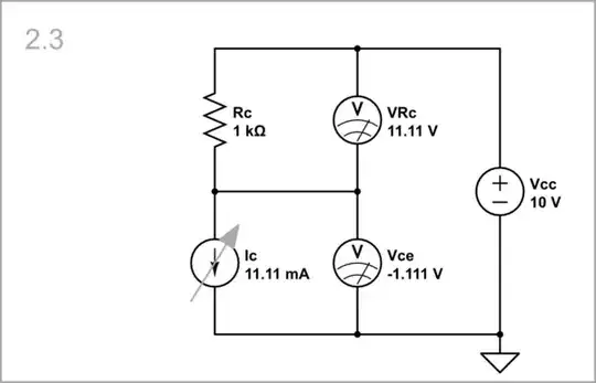
"Saturation": At the maximum current of 10 mA, the current source is "saturated", and the voltage across it is zero.


True current source: But if this is a true current source producing more than 10 mA, the voltage will go below zero.

Transistor circuit
Finally, we repeat the same experiments with a real transistor and see that the results are the same (there is only a difference in the shape of the curves determined by the transfer characteristic of the transistor).
Active mode: The transistor can control the output voltage from 0 V to Vcc.


Saturation: The transistor cannot control the output voltage; it is just a "piece of wire".
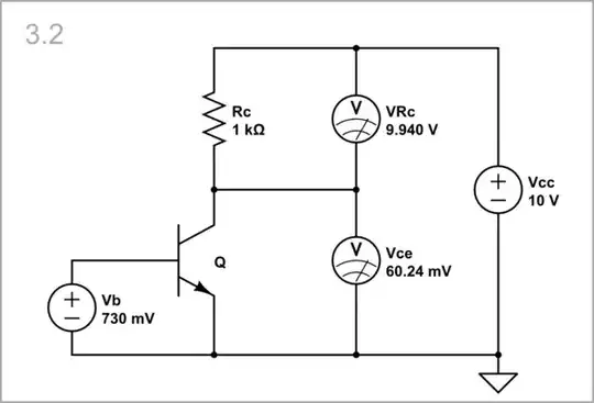

“Negative transistor”: To bring it out of saturation, we can apply the negative resistance trick by inserting an additional negative voltage source Vee in the emitter.


Circuit fantasist
- 16,664
- 1
- 19
- 61