Uniform resistance
I have read that resistance is proportional to resistivity and length of the material and inversely proportional to the area of the material.
This property (R = ρ.l/A) is only true for conductive materials with a uniform resistance distribution. Typical examples are metals, graphite, etc.
Some history: In the early 90's, I was obsessed with the idea of using conductive foam to make all sorts of "rubber resistors". It was particularly useful for educational purposes, for example to illustrate connecting resistors in series and parallel, voltage dividers, bridge circuits, etc.
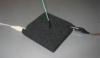
CircuitLab experiments: Now I wondered if this could not be done with CircuitLab and hastily fabricated the story below. I have used as a basis an IEC resistor with unit length, area and resistance. Using a current source I and voltmeter R(kΩ) I have made a DIY ohmmeter. The voltmeter reading is in volts, but consider it to be in kohms.
Variable length
l = 1; A = 1; ρ = 1: First we connect a single resistor R1. The voltmeter shows 1 V, which at a current of 1 mA corresponds to a resistance of 1 kΩ (the measured corresponds to the actual).
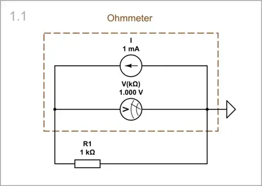
simulate this circuit – Schematic created using CircuitLab
As you can see from the graph below, the voltage across the resistor is proportional to the current.

l = 2; A = 1; ρ = 1: Then we increase the "length" two times by connecting another single resistor (R2) in series. The resistance increases proportionally two times.
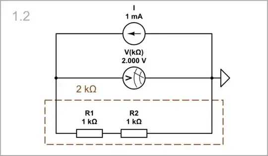
simulate this circuit
l = 3; A = 1; ρ = 1: Finally, we increase the "length" even more by connecting another single resistor (R3) in series. The resistance increases three times.
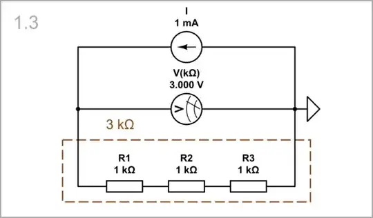
simulate this circuit
So, we conclude that resistance is proportional to length.
Variable area
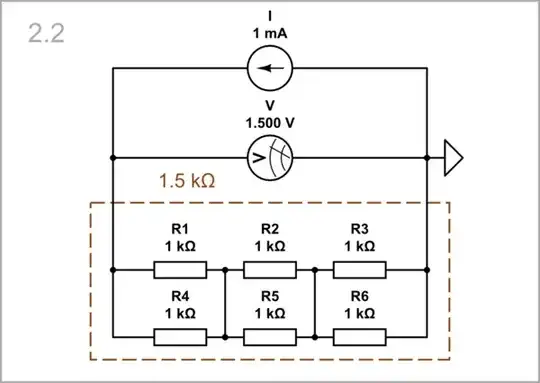
l = 3; A = 2; ρ = 1: Now let's increase the "area" two times by connecting another string of resistors (R4, R5 and R6) in parallel. The resistance decreases two times.

simulate this circuit
l = 3; A = 2; ρ = 1: We can connect the same midpoints between resistors since their voltages are equal. We can even imagine that the same points inside resistors are connected.
simulate this circuit
l = 3; A = 3; ρ = 1: Finally, we increase the "area" three times by connecting another string of resistors (R7, R8 and R9) in parallel. The resistance decreases three times.
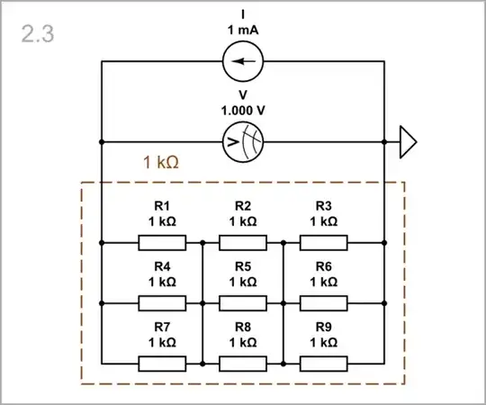
simulate this circuit
So, we conclude that resistance is inversely proportional to area.
Variable resistivity
l = 3; A = 3; ρ = 2: I have imitated the resistivity by the resistance of the single resistor. So, to increase the resistivity two times, we have to increase the resistance of each resistor two times. As a result, the total resistance increases two times.
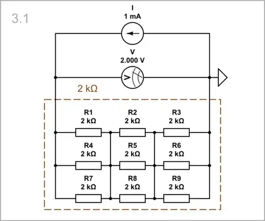
simulate this circuit
l = 3; A = 3; ρ = 3: Finally, to increase the resistivity three times, we increase the resistance of each resistor three times. As a result, the total resistance increases three times.

simulate this circuit
Our conclusion is that resistance is proportional to resistivity.
Non-uniform resistance
... resistance changes/decreases. How is this possible when length, area and resistivity are constant?
Resistance is not always related to the geometric dimensions and it is not appropriate to talk about resistivity, length and area in this case. Here is an unconventional example.
I have made a (virtual) 1 kΩ resistance using an opposing behavioral voltage source whose voltage V [V] = 1000*I[mA] is controlled by the current flowing through it (ie it is a current-to-voltage converter).
Obviously, this resistance has no resistivity, no length and no area.
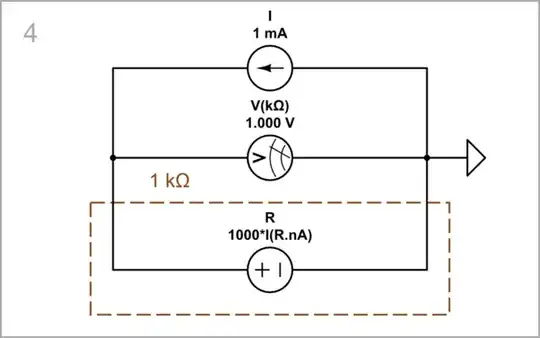
simulate this circuit
As you can see from the graph below, the voltage across this virtual resistor is proportional to the current like in the real resistor in Schematic 1.1.


