General Information About the Project
I am trying to design a zero-crossing detector circuit for convert the sinusoidal signal from an ultrasonic transducer to a square wave. Here is the image of ultrasonic transducer:

To trigger the transmitter transducer I generate 40kHz square wave with SG3525. Square wave is 12Vpp and duty cycle is 49%. Oscilloscope output shown below:

When I drive the transmitter with this pwm wave, I can read the signals from receiver sensor. Regardless of the location of the transmitter, the receiver always receives a signal at a frequency of 40kHz. What changes is the amplitude value and phase shift. Here is the receiver signal outputs below:

These measurements performed at different times, so frequency values of transmitter and receiver shown not equal. Even if their frequency values don't look compatible, they are compatible.
Zero-Crossing Detector
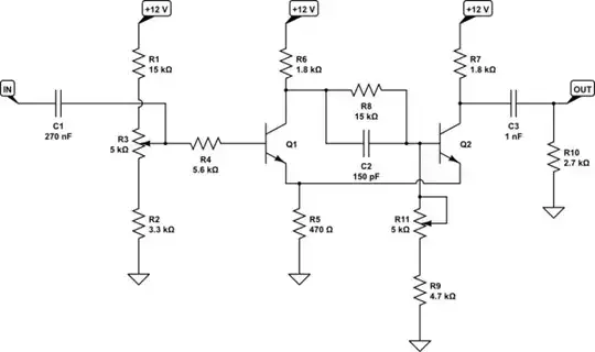
I want to convert the receiver's sinusoidal signal into a square wave to analyse the phase-shift between signals of transmitter and receiver. I used a Schmitt Trigger circuit, but it created a phase shift and could not successfully convert the sine wave into a square wave. Then, I decided to build the circuit with BJTs. The circuit that I built, and the output shown below:

simulate this circuit – Schematic created using CircuitLab

Experiment
I tested the circuit shown above on a breadboard and analyse the circuit with an oscilloscope. My test steps are as follows:
- I test the circuit with function generator with different voltages and frequencies.
- I test the circuit with the receiver's output signal.
1st Experiment with Function Generator
When I analyse the circuit, I applied the voltage values from 1V to 10V and frequency value from 1kHz to 40kHz. When I apply a frequency value above around 5kHz, the square wave produced by the circuit begins to distort. Here are the images:
for 10Vpp and 1kHz:

for 10Vpp and 7kHz:

for 6Vpp and 40kHz:

2nd Experiment with Receiver
I tested the signals of receiver to convert them into square waves. To trigger the receiver, I used the SG3525 PWM circuit and transmitter. Bu it does not work on the circuit. I read sinusoidal 40kHZ 3Vpp wave from receiver. Then I connect the signal into the circuit to examine the conversion, but it did not work.
Results
When I feed the circuit with a sine wave using the Function Generator, I can receive a square wave at low frequencies. But when I increase the frequency (about 2-3 kHz and above) the square wave starts to distort. When I give the signals from the receiver to the relevant circuit, I cannot get any output. Not even a distorted signal occurs.
Question
I want to convert the sinusoidal wave coming from the receiver into a square wave, compare it with the wave I created in the transmitter, and obtain the phase shift by looking at this. However, the circuit I built to convert the sinusoidal wave into a square wave is malfunctioning at high frequencies. At the same time, this circuit does not even process the signals coming from the Receiver.
If this method I have applied is a logical method to see the phase shift, why can't I process the receiver's signal? If you know a more logical way to see the phase shift, I would be happy if you share it with me.
Best regards
