0

I'll be powering a Raspberry Pi Zero 2W, and want to be able to power it for a while using an 18650 cell. But as rechargeable batteries are a fire risk, I want to be a bit more sure I didn't miss anything.

I looked into a couple of off the shelf solutions.

Pimoroni LiPo SHIM - does not support charging an off the shelf MH-CD42 charging board - No schematics available. I don't fully trust that it properly handles in-circuit charging (charging while running the Pi).

I used a couple sources:

I checked my circuit multiple times, and think it should work. Did I miss anything? Is this circuit safe?

If instead of using an op-amp I'd go for two cells in series, what circuitry would need to be doubled? Where are some good sources to read into this more?
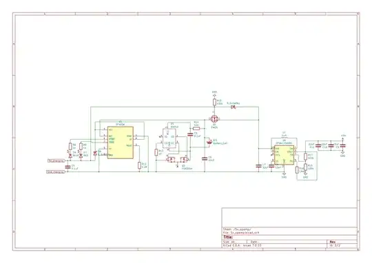
My schematic again

  • 1
    The opamp has pin 1 not connected. And I don't see what should be it's function, why not connecting the 5V rail directly to the mosfet gate? Also, you can power the pi zero with 3.3V, if I'm not wrong, so it would be easier to use just an LDO instead of the boost converter, unless you need 5V for something else. – Gos Jan 01 '24 at 20:32
  • @Gos thanks, I indeed messed something up there. I fixed the schematic in the question. The opamp was there, bluntly said, because I copied that part from https://github.com/gbhug5a/Solar-Power-Load-Sharing/blob/main/OpAmpVersion-Revisited-rev2/OpAmp%20Version%20Revisited%20-%20rev2.pdf , but it indeed seems like in my application it's not required. When the 5v is connected, it's regulated 5v, not a solar panel. – Daniël van den Berg Jan 01 '24 at 21:21
  • @Gos as for the pi zero running on 3.3v, do you actually have a source for that? I've looked into it, but can't find anything official. The only official specs I can find is the product brief, which mentions 5v 2.5A: https://datasheets.raspberrypi.com/rpizero2/raspberry-pi-zero-2-w-product-brief.pdf. https://raspberrypi.stackexchange.com/questions/47421 does say so, but nothing official as far as I can find. – Daniël van den Berg Jan 01 '24 at 21:22
  • 1
    @Gos The Raspberry Pi Zero 2 W Schematics show a PAM2306AYPKE taking a 5 V supply and generating the 3.3 V and 1.8 V supply rails for the Raspberry Pi Zero. I.e. looks like do need a 5 V supply. – Chester Gillon Jan 01 '24 at 21:36
  • 1
    @Chester, yes, you are right, I was not sure. Maybe feeding the battery voltage directly into the 5V input would work, as the processor and most of the board need 3.3v or less. Except for the peripherics that need 5V. – Gos Jan 01 '24 at 21:45
  • 1
    Another thing you could consider is putting a resistor before the mosfet in the 5V rail connected to ground, something like 100KΩ. Otherwise, when you are not charging the battery and there is nothing connected, the 5V rails would be floating and the voltage could be different than zero, and then the mosfet could be eventually not fully activated. It's not a big issue but I think that you could have more resistance and voltage drop in the mosfet from drain to source. – Gos Jan 01 '24 at 22:03
  • Wait... I'm looking at it on my phone now, but I just managed to flip my mosfet, didn't I... And @Gos I assumed the connection to the vcc of tp4056 would keep the 5V rail from floating when disconnected, or does it not work that way? (Software engineer by trade. If only electronics were as simple as binary logic...) – Daniël van den Berg Jan 01 '24 at 22:14
  • Trivial and irrelevant to circuit function, but it would be better for the gate connection to Q2 pin 5 right hand / source side just so that people mentally pick up the circuit functioning and immediately. This may be in a schematic footprint and not easily changed. – Russell McMahon Jan 02 '24 at 01:15
  • No, the mosfet was rigth, now is wrong. The internal diode should point to the right. It is to prevent that the current goes backwards to the TP4056 when there is power in the 5V rail. And when there is no power in the top rail then the mosfet is activated and you get less resistance and less voltage drop, but in both cases it conducts in the direction of the internal diode. I also do electronics as a hobby, and this analog circuits sometimes are like an arcane science. You drop a capacitor here, a resistor there... and it does some magic :-) – Gos Jan 02 '24 at 07:22
  • when the power is disconnected the TP4056 is off, I'm not sure what happens with the 5V rail then. I saw the recommendation of the resistor somewhere and I applied to my circuit time ago. It makes sense, but maybe is not a big issue. In the worst case if the mosfet is not fully activated it will still work, but consume a bit more and lose a bit of voltage range from the battery. – Gos Jan 02 '24 at 07:29
  • Yes. No. :-) || ie I was not questioning the MODFET orietation - ONLY where pin 5 connects to the device. I mean that pin 5 should be SHOWN above pin 6 as the gate acts relative to the source (simplistically) . NO change in actual connection was intended. || I have used a single reverse FET as polarity protection in a commercial product. 100-200 thousand made. A "nice trick". – Russell McMahon Jan 02 '24 at 07:29
  • @Rusell, sorry, I was answering the previous comment, where the OP flip the other mosfet, Q1. Your comment is ok. Sorry for the confusion. – Gos Jan 02 '24 at 07:33
  • OK - I've now made this so may as well post it - gate change https://i.stack.imgur.com/Sni9I.png :-) – Russell McMahon Jan 02 '24 at 07:40
  • @RussellMcMahon changed ;) – Daniël van den Berg Jan 02 '24 at 08:39
  • @Gos thanks, so it should be in the correct orientation now again. Diode blocking current from S to D, preventing "backfeeding" when the 5v line is active. I honestly need to stop touching the keyboard until I know all the shortcuts.... ‍♂️ – Daniël van den Berg Jan 02 '24 at 08:41

0 Answers0