4

I need to design an E-stop system - any number of normally closed switches, anywhere from one to possibly as many as 30 identical pieces of equipment that all need to be informed of a switch opening, everything connected in a single loop. Surely this is a standard thing to do, but I think I'm just not using the right search terms - every variation on "broken loop detector" I've tried is just showing me traffic detection systems, and various forms of invisible fences.

I suppose the simplest implementation would be to use an external power supply for the loop, and an optoisolator in each unit (which could be of the AC-input variety, so that the polarity of the loop terminals doesn't matter). The problem is that the power supply would have to have a fairly high voltage to run 30 optoisolator LEDs in series - but in the more common case of the system only having one or two units, something would have to burn off most of that voltage. (I don't consider an adjustable power supply acceptable, as I couldn't trust that the end-user would adjust it appropriately.)

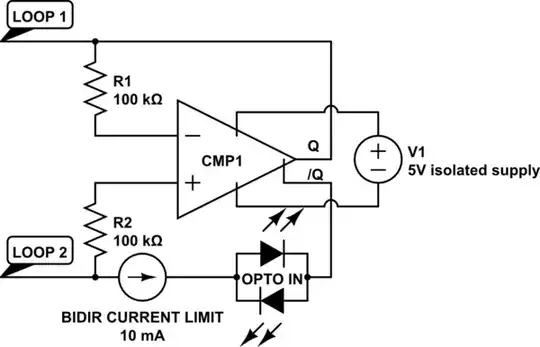
I don't like the idea of requiring a separate loop power supply, anyway - the equipment units themselves should be the only things the user needs to install. So I was wondering if there's some clever way of having each unit push just enough voltage into the the loop to light one LED, somehow adapting to the existing polarity of the loop, so that there's no great excess of power to be burned off? The best I've come up with is this crazy circuit, using a complementary-output comparator (LT1713, for example) as a power source with controllable polarity:

schematic

simulate this circuit – Schematic created using CircuitLab

The idea is that the circuit senses and opposes whatever voltage might already be on the loop; it needs some hysteresis (not shown) to work when there's only one device. R2 has to have a fairly high resistance so that there's no way that current through the comparator's input pin can possibly light the LED; the current has to pass through the loop.

I suspect that this would be prone to oscillation if multiple instances were looped together, but I haven't had any luck trying to simulate it - LTSpice does not like floating isolated circuits, apparently.

jasonharper
  • 389
  • 1
  • 2
  • 7
  • 5
    Your question title mentions "emergency stop" and this usually indicates some safety requirement which, in turn, implies a fail-safe arrangement which an opto-isolator on its own will not satisfy. What is the nature of the equipment being switched? – Transistor Dec 24 '23 at 06:12
  • 2
    Are you t wanting to buy and use safety relays or are you trying to design one? – Jasen Слава Україні Dec 24 '23 at 06:50
  • 2
    every variation on "broken loop detector" ... try searching for what you are asking about Emergency stop switch loop circuit – jsotola Dec 24 '23 at 08:49
  • Nresistors in series in a loop. Tripping station applies a voltage in place of its resistor. All stations see voltage of V/n-1) across their resistor. For failsafe apply a lower voltage always. Tripping station adds to this. If standby voltage is less than Vfailsafe/N there is a hi z or open fault. || As long as Vf_LED x N + some more can be provided then just having any station applying this to series LEDs will work. Voltage can be provided by small boost converters if desired. Making anything failsafe takes some work. || A digital polling system can be not very costly and work well. – Russell McMahon Dec 24 '23 at 12:34
  • 3
    Which market(s) is the product intended for? That could affect which safety standard(s) it needs to be certified for. – Chester Gillon Dec 24 '23 at 13:01
  • 2
    Is there any SIL requirements? What is most dangerous? Erroneous trip or malfunction when pressed? – vidarlo Dec 24 '23 at 18:13

5 Answers5

10

Safety relays are a thing you can buy off the shelf (in DIN rail enclosures at typical industrial electrical engineering prices).

They are designed to operate on a 20mA loop circuit.

Get several two channel safety relays and set up a two loops one with current flowing clockwise and the other antclockwise

In this way if the loop is broken or grounded all the relays will see an interruption of the current.

Arrange for your E-stop switches to break both loops.

In this way you should be safe against any single point failure.

Most important of all: don't take security advice from some yobbo on the internet wha has no skin in the game.

Transistor
  • 175,532
  • 13
  • 190
  • 404
  • see my answer. I quote you :-). – Russell McMahon Dec 24 '23 at 12:46
  • 5
    +1 from me. An e-stop circuit isn't the time to use those sweet design and breadboard skills. Rather, it's the time to buy off the shelf products and use each one exactly as intended. If resistors or op-amps enter the conversation, it's already gone wrong. Your business and/or license and/or job could depend on it. – Aldus Bumblebore Dec 25 '23 at 00:22
  • peples lives are on the line, your freedom could depend on if you are found guilty of gross negligence (but I'm not a lawyer) – Jasen Слава Україні Dec 25 '23 at 07:31
2

Simple and easy:

Nstations in a loop.
Resistor at each station.
Voltage feed from master station causes a voltage drop across each resistor. This could instead be a constant current if desired to allow variable number of stations BUT absolute value of voltage does not matter - see below.

Tripping station opens loop. All stations see zero voltage across their resistor.
This could if desired be an LED as mentioned.
Or a differential amplifier at each station to allow absolute voltage to vary.

Resistor detector is failsafe for whole loop integrity as long as the differential amplifier functions or, if optos are used, as long as the opto output does not fail ON.

Jasen's system is costlier BUT better.
Almost as he says "Do your own due diligence when receiving security advice from some yobbo on the internet who has no skin in the game :-).

This system is not fail safe for an individual station failing to open its loop when it should. It's hard to design a system that is. You can trigger occasional short duration "proof of life" events but that just moves the failure point further inside your station.

Russell McMahon
  • 150,303
  • 18
  • 213
  • 391
  • The whole point of my question is that I'm trying to avoid the need for a "master station". I don't want to have to stock two different versions of the equipment. I don't want there to be any problems for the users to join two small systems into one big system, or split a big system into two, if that's what meets their immediate needs. – jasonharper Dec 24 '23 at 17:51
  • you need a master node else if the loop gets shorted to itself it ends up as two loops. – Jasen Слава Україні Dec 25 '23 at 07:38
  • @jasonharper For a master feed you need about N_stations x Vstation (as we both know) . If optos are the inputs ( eg 4N25 ) then you nee 30-45V. An LM317HV rated at 60V max will allow a simple constant current feed to from n 1 to 30+ opto input stations. || If you use resistors and differential amplifiers you could use far lower voltage drop per station. – Russell McMahon Dec 25 '23 at 10:15
  • 1
    @jasonharper, many of those who have responded to your question have raised questions about the level of safety required for your application and you haven't addressed these concerns. Can you edit your question to fill in the missing details? – Transistor Dec 26 '23 at 01:51
1

You can buy a safety controller that will handle sending power through your safety circuit and monitoring it, with outputs that you can then hook up to contractors to cut power to the equipment if the loop is broken. That's probably the easiest way to go. (You can get fancier with safety PLCs, but you don't need that for your scenario.)

For the switches themselves, mechanical contacts are the norm, and normally doubled up (i.e. each EMO button has two switches attached to them with your loop going through both of them) to make things likely to work even if a contact gets welded closed.

IceGlasses
  • 349
  • 1
  • 5
0

A long series loop of switches will be plagued by false openings that shut off the equipment. A string of parallel switches doesn’t inherently confirm wiring continuity to the switches. A parallel scheme that uses a fixed resistor shorted by a switch and detected by a current bridge (comparing it to another resistor) has neither defect, and pinpoints the source of an alarm/emergency shutdown allowing the system be be maintained. Also, avoid using 5v high impedance signaling for this kind of equipment. The currents induced by stray magnetic field from electric motors that are terminated in a high impedance results in voltage noise that exceeds the common mode range of an op-amp/comparator.

  • 2
    "A long series loop of switches will be plagued by false openings that shut off the equipment." I work in systems that have 20 to 30 E-Stop buttons in series and this architecture has easily been in use reliably for 30+ years, so I am not sure why you are experiencing what you state. – Peter M Dec 25 '23 at 19:13
-1

An arrangement I've seen suggested for some safety-related applications (though I don't know what regulatory requirements it does or does not satisfy) is to have a current-limited power supply drive a pair of wires which is routed to each switch in sequence, and finally to a relay, or perhaps a pair of relays which both needed to be energized to enable the device. Any switch in the chain may short out the supply (since it's current limited) or open either leg, and a short-circuit fault or open-circuit fault anywhere in the chain will trigger an emergency stop. If everything on the chain is floating relative to everything else in the universe, the only kind of faults that could prevent any device on the chain from triggering an e-stop would require that at least two parts of the chain be shorted to something else which could bridge over an open part of the chain.

Note that when wiring such a chain and using short-on-fault switches, one would ideally use switches that have four terminals--two at each end of the contact, and wire the circuit so that current passes through both pairs of terminals. That would ensure that if a wire comes off a switch terminal, it will trigger an e-stop rather than leaving the switch inoperable.

supercat
  • 46,736
  • 3
  • 87
  • 148