4

R85 in the following circuit keeps getting burned out when the photo-triac is turned on. It may last for a few minutes before burning out. It is a smallish 1/10 W resistor, while R83 is in DIP package.

I am confused about what's causing R85 to exceed its power rating. AC_HOT is 220 VAC. The load is an inductive load (an incline motor, rated at 15W).

Is there anything in the following circuit that does not make sense? Any pointers are appreciated.

enter image description here

BT137-600E datasheet

PC1S3063NTZF datasheet

Dave Tweed
  • 172,781
  • 17
  • 234
  • 402
Brian Wang
  • 503
  • 2
  • 6
  • 16
  • Where is the load connected? – Andy aka May 14 '13 at 11:36
  • The load is across LUG10 and AC_NEUT. I have edited the post. Thanks. :-) – Brian Wang May 14 '13 at 11:54
  • If you include links to the datasheets for the components you're using, it makes it a lot easier on people who might be interested in answering your question. – Dave Tweed May 14 '13 at 11:57
  • How is the gate current supposed to be limited? Aren't you going to get 10ma * 220V = 0.2W through it? – pjc50 May 14 '13 at 12:11
  • @DaveTweed Thanks. I will include the links next time. :) – Brian Wang May 14 '13 at 12:18
  • If that resistor is burning up, you must be forcing something on the order of 100 mA RMS through it, which is also close to the absolute maximum for the optocoupler. Was this circuit originally designed to handle inductive loads at 220V? Keep in mind that with reactive loads, the zero crossings of the current do not align with the zero crossings of the voltage, and this puts a lot of stress on this type of circuit, which is often rated "for resistive loads only." – Dave Tweed May 14 '13 at 12:19
  • Dave is quite correct. For inrush current avoidance (when the magnetic material of the inductive core saturates) you need to switch the circuit initially when the 220VAC is near a peak NOT as it passes thru zero. – Andy aka May 14 '13 at 12:31
  • We have also tried Q6008RH4, which is a High-Comm triac, while BT137 is an ordinary 4Q triac. With Q6008RH4, the resistor does not get burned or not as easily (we have not seen it burned yet). I think there is something fundamentally wrong with the circuit. I am not sure about the values of the resistors and how much current flows through them. – Brian Wang May 14 '13 at 12:37
  • @DaveTweed Do you mean that excessive voltage spikes when the gate of the TRIAC is being turned on and off is causing the resistor to burn up? I tried hooking up a scope but the waveform of 220V AC gets clipped... I also tried to measure the current flowing through R85 but my DMM has trouble measuring the short pulses. I did put the scope across R85 and saw a max of 0.7V. If my calculation is correct, that does not exceed the resistor's power rating. How/Where do I measure/observe the stress on R85? Thanks. – Brian Wang May 15 '13 at 01:02
  • @pjc50 Could you elaborate a bit more about the gate current? Thanks. – Brian Wang May 15 '13 at 01:03
  • Have you read the Wikipedia article about TRIACs? It has a lot of detail that I think is relevant to your situation, particularly the part about commutating. I think you're getting very large, very narrow spikes of current through the gate resistor each time the main triac tries to turn off at a current zero-crossing. – Dave Tweed May 15 '13 at 15:52
  • @DaveTweed I think that's it! That's why 3Q TRIACs do not fry the resistor. I guess for the circuit to work with 4Q TRIACs, a proper snubber RC should be added. Thanks for the pointers. – Brian Wang May 16 '13 at 01:29

2 Answers2

2

The datasheet for the triac says the average gate power is .5 watts. You need a resistor rated for at least that. Also, If we look at the Triac wikipedia it discusses that 3Q triacs are designed to operate heavily inductive loads. This would explain it functioning better. Normal TRIACs or 4Q triacs have problems due to high voltage and current angles when they turn off at zero crossing. They experience a voltage spike which can turn them back on again. Commutations (▲v/▲t) can be improved with the use of snubber networks. They are designed to provide at need to help balance the circuit. With the introduction of 3Q triacs this problem was avoided. If shopping for a device like this you can simply search for "Snubberless Triacs" which is what they are often called.

hondabones
  • 89
  • 1
  • 5
0

There is nothing wrong with your schematic that I can see. The gate resistor should only dissipate a few milliwatts average, since it stops conducting once the triac turns on. (10mA for a couple microseconds every 1/2 cycle).

What do you mean "DIP" package for R83- I would expect that to burn up first if it had a similar rating.

I wonder if you have the triac wired incorrectly, or if one of the parts is defective.

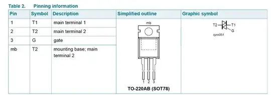
Make sure the triac wiring is correct. The view of the package is from the top.

enter image description here

If the triac gate is shorted to the MT1 or the triac is damaged such that it never triggers, you will see something like what you have observed, however R82 will see a lot more power dissipation.

If you still need help, posting a photo of the circuit would not hurt.

Spehro Pefhany
  • 397,265
  • 22
  • 337
  • 893