I don't know how to how to properly wire the two outputs of the driver IC TC4431 to the MOSFET gate.
In the datasheet, there's a test circuit diagram (@page7, FIG4-1), should I connect the outputs together to the gate pin? Since resistors might be needed to fine tune Turn-On and Turn-Off timings on the actual PCB (as mentioned in page 6), I need to consider placing spaceholder pinouts (If not needed I'll populate with 0 Ω resistors). Which is the right wiring or should the resistors be pull-up pull-down as it's common on MOSFET gates (and left unpopulated if not needed)?
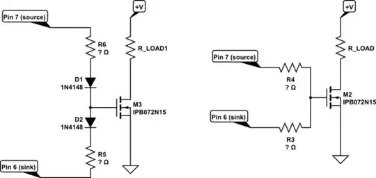
simulate this circuit – Schematic created using CircuitLab
Datasheet: TC4431
