2

I'm working on a project that involves displaying the following words on three 7-segment -displays.

  1. A S U
  2. F O E
  3. C S E
  4. F U N

Each word should transition to the next after a one-second interval (I know how to implement this).

I made it by creating a truth table for each display and implemented it using logic gates. For instance, inputting 00 to the 3 displays results in showing "A S U," inputting 01 shows "F O E," and so on.

However, I believe there might be a more efficient, less cluttered approach to have a set of characters on each screen, without using EPROM or microcontrollers.

All suggestions would be incredibly valuable to me, especially since this is my first experience with electronics!

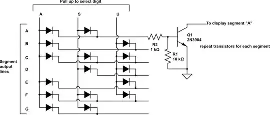
Here are my circuits, where each display has a set of characters: enter image description here

enter image description here

enter image description here

Here's the schematic for the first display, where it has a set of characters (A,F,C,F) that it shows depending on the input value:

00: A

01: F

10: C

11: F

enter image description here

Michael
  • 21
  • 3
  • Could you provide a schematic instead of a breadboard wiring diagram? – JYelton Dec 05 '23 at 22:53
  • You'll need to supply proper schematics for the grown-ups here. Those are "cartoons" and don't show the "schema" of the circuit. The program that generated them may be able to generate a schematic but you'll have to spend some time tidying up the rats' nest of wiring. – Transistor Dec 05 '23 at 22:53
  • @Transistor very sorry about that, I'm a complete beginner and never interacted with circuits before. Check the edit. – Michael Dec 05 '23 at 23:08
  • 1
    A very warm welcome to the site. Thanks for adding the schematic, that's much easier to follow. The previous wiring diagrams weren't suitable because every reader would have to know the IC pin-outs then slowly construct the schematic in their head, which makes it all so difficult. – TonyM Dec 05 '23 at 23:13
  • 1
    @TonyM Thanks, I didn't know that! Makes a lot of sense. – Michael Dec 05 '23 at 23:16
  • Connecting most-used segments together directly in parallel is not a good idea. Minor variations in the properties of the individual LEDs leads to variations in brightness as some segments hog the available current. Better to have 7 resistors for each display, 1 per segment, and tie together the driving points of the resistors. – AnalogKid Dec 05 '23 at 23:59
  • At some point you're going to need diode OR-big since you have multiple inputs driving common outputs (the segments). Whether you accomplish this with diode ROM as I suggested in your last question or with K-maps and a whole bunch of individual gates, the result is the same but I stand by my previous assertion that diode ROM is the easiest and most straightforward way to get where you want to go, given your restrictions. – vir Dec 06 '23 at 00:25
  • Thats "diode OR-ing" by the way. I wish computers had the ability to feel physical pain sometimes. – vir Dec 06 '23 at 00:33
  • Maybe you can find a ROM that does what you want already, perhaps you can use a 7 segment decoder but connect inputs and the segments differently – Jasen Слава Україні Dec 06 '23 at 02:31

1 Answers1

1

I would use a diode ROM something like this:

schematic

simulate this circuit – Schematic created using CircuitLab

This would work with common-anode displays. If you pull line "S" high, segments A, C, D, F and G will be lit. You can add more vertical lines and diodes for more display patterns.

I'll leave the digit/letter selection logic as an exercise for the student :-)

Peter Bennett
  • 59,212
  • 1
  • 49
  • 132
  • The other strategy for common-cathode displays is to use a PNP to supply each of the "letter" lines and have each "segment" line connect to the display through its own current limiting resistor. The transistors have to be a bit beefier since they're supplying all the segments simultaneously but in this case you only need three. – vir Dec 06 '23 at 01:53