1

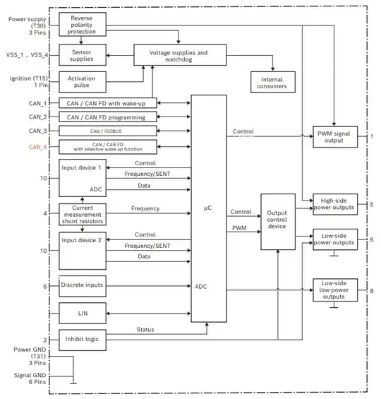
My understanding is that MCUs (especially 32 bit ones) typically operate at 3.3 V. I have a 24/12 V, 32 bit automotive ECU (Bosch Rexroth Series 40). I've provided them as an example, but I'm asking generally about all automotive ECUs. Their datasheet includes a block diagram as follows:

Block diagram of the Bosch Rexroth Series 40

This leads to my questions:

  1. Does the "Voltage supplies and watchdog" block step-down the supply voltage to 3.3 V for the μC block?
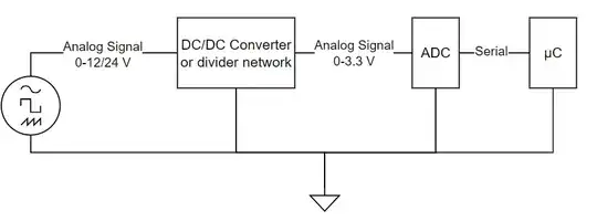
  2. Do the ECU input conditioning blocks step down the voltage before feeding into a 3.3 V ADC? I've included another diagram to visualize what I mean. Conversely, are outputs stepped up from 0-3.3 V to the appropriate 0-12/24 V using amplifiers?

An analog signal being fed into a DC/DC converter or resistor divider, which leads into an ADC, which transmits serial communication to the μC

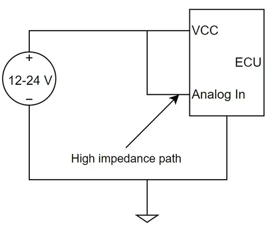
Edit: Thanks for the comments. For context, I'm specifically asking about the internals of the ECU (MCU block and peripherals,,) not about external sensors and their supplies. Below is an application that I'm using this controller for. It monitors the supply voltage for undervoltage and uses the supply voltage for calibrating parameters in firmware. As you can see, it does not rely on the sensor supply outputs. It is purely reading the supply voltage.
The ECU is supplied by 12-24 V while also reading the supply using an analog input pin

Max F
  • 13
  • 3
  • Why do you think cars use 12V? I have driven cars which have a 48V as it's battery, and others with 415V. You're used to a 12V lead acid battery which is used to power the lights etc. That is because that's a convient votlage for those devices. This voltage gets stepped down to something useful for each device. For example in the radio it gets stepped down to 1.8V or even 1V for the components in it, the same goes for the ECU. Like your computer at home, it gets 110V/220V AC in, it gets stepped down to a useful voltage inside the computer. – Puffafish Dec 05 '23 at 17:15
  • More or less, yes. Did you want a more specific answer to any of these questions? – Tim Williams Dec 05 '23 at 17:15
  • Here's a better link for the datasheet... According to this datasheet, there are four VSS pins that can be used for referencing: VSS1 to VSS4, stands for "Voltage Sensor Supply", contrary to normal reference nomenclature, VSS1 to 3 says it outputs 5V and 4 outputs 10V. You'd need a separate PMIC to step down to 3.3V. –  Dec 05 '23 at 17:16
  • Some questions which may help you: https://electronics.stackexchange.com/questions/6403/whats-up-with-the-operating-voltages-5-v-3-3-v-2-5-v-1-8-v-etc and https://electronics.stackexchange.com/questions/665524/what-is-the-reason-some-microcontrollers-are-designed-to-be-powered-with-5v-or-3 – Puffafish Dec 05 '23 at 17:18
  • We can't know how this specific device or similar devices work. It might use 3.3V or some other supply. Sometimes inputs are externally divided before ADC, sometimes you feed higher voltages directly to ADC, and it depends on ADC. Outputs might not be stepped up with amplifiers, just driven with transistors through level shifter - but whether you count that as an amplifier is another thing. Unless you find schematics or open the ECU and do measurements and reverse-engineering, these questions cannot be answered. – Justme Dec 05 '23 at 17:43
  • @TimWilliams Thank you, that answers it fine. I'm looking for some reference designs if you know of any. If you respond with an answer, I will mark is as correct. – Max F Dec 05 '23 at 17:48
  • @Colin Thanks for the additional info. I've edited my question to include some further details. I'm just interested in the internals and if Automotive ECUs typically run at 3.3 V internally, not the sensor supplies. – Max F Dec 05 '23 at 17:49
  • @Justme Thanks for laying it out. I understand that it's not possible to know the internals, I'm asking generally about automotive ECUs and provided this one as an example (as indicated in the original post) since they have a block diagram. – Max F Dec 05 '23 at 17:50
  • @Puffafish Cars as a whole may not operate at 12 V, but that is a common voltage level for valves, pumps, etc. supplied by Tier I & II suppliers. It's typically achieved using a DC/DC converter. For context, I'm working on electric vehicles so there are many bus voltages present. – Max F Dec 05 '23 at 17:52
  • Cars don’t operate at ‘12V’. The lead-acid state of charge varies and can range between 11 and 14V or so. Also, when the alternator runs this adds noise to the battery rail. – hacktastical Dec 05 '23 at 22:03

1 Answers1

2

It’s impossible to make a blanket statement about what voltages the MCU will actually use - you need to consult the MCU datasheet.

That said, 5V and/or 3.3V are common for logic I/O voltages, it's highly likely that the MCU has at least this voltage rail. The MCU core voltage for a newer, more advanced MCU could be lower, such as 1.2V or even lower than that. This is compatible with more advanced process nodes.

As for what voltage range the MCU’s ADC supports, again you’d need to consult the data sheet. In any event the sensed voltages will need to be scaled to what the ADC can accept.

If you are looking to use a power rail for the voltage reference, it would seem prudent to instead provide a dedicated reference that is stable and also qualified for automotive.

hacktastical
  • 53,912
  • 2
  • 49
  • 152