1

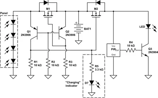
See the attached circuit diagram and PCB design. All I'd like to do is have a very small LED turn on when the panel is charging the battery.enter image description hereenter image description here

Circuit description: Q1, a PNP transistor ensures that when the solar panel has a potential difference (it's in the sun), the LED cannot turn on and the battery is being charged. The PIR is a Passive Infrared Sensor which, when triggered, sends a 3.7V signal, which turns Q3, an NPN transistor "on" and allows the batteries to drive the large LEDs (bottom right).

Andrew Earl
  • 113
  • 5
  • 1
    What does the board you show do? I'm a bit confused because there's a component labeled "PIR" in there. – Marcus Müller Nov 28 '23 at 08:50
  • Ah right, I'll edit in a description, another site took down my description so I was worried it was superfluous. – Andrew Earl Nov 28 '23 at 08:52
  • 1
    Ok cool! Thanks for the description. But: you already have designed something that turns on a sensor when the solar-supplied voltage is above that of the battery. Isn't that exact same condition that which you need to turn on the LED? – Marcus Müller Nov 28 '23 at 09:01
  • I think Q1, PNP transistor does the opposite of what you're saying, right? When the panel voltage is high, the sensor cannot turn on because the current will not be flowing across the Q1? Also, "LED" on the bottom left refers to the higher power LED lights, I'd like a small low power LED just to indicate charging. – Andrew Earl Nov 28 '23 at 09:04

1 Answers1

1

I see a number of problems with your circuit. I would propose a slightly different approach, based on the "ideal diode" circuit found in Automatic Power Selection with MOSFET

schematic

simulate this circuit – Schematic created using CircuitLab

When the panel voltage is above the battery voltage, Q1 is on and Q2 is off. These switch M1 on and M2 off. The "Charging" indicator is lit.

When the panel voltage drops below the battery voltage, Q1 switches off and Q2 switches on, which in turn switch M1 off and M2 on, enabling the PIR and main LED.

Note that I'm assuming that the PIR output is a voltage, not a current, so R4 needs to be in series with Q3's base, not in parallel with it.

Dave Tweed
  • 172,781
  • 17
  • 234
  • 402
  • Logic:
    • Panel voltage > batt voltage: Q1 ON because Ve > Vb < Vc. Current flows to charging indicator. Not sure why Q2 OFF here, as Vb < Ve? M1 is ON because negative voltage between G and S, thanks to the forward biasing Diode and panel voltage. M2 is now off because voltage between G and S is positive, due to battery and panel voltages across G and S.
    • Panel voltage < batt voltage: Q2 ON because Ve > Vb < Vc. M1 therefore off because G and S no longer negative voltage. I'm not sure about Q1 OFF. M2 is on, because there is negative voltage between G and S, enabling PIR and main LED.
    – Andrew Earl Nov 29 '23 at 09:58
  • ^ trying to keep the above comment within the character limit, apologies if it is confusing. – Andrew Earl Nov 29 '23 at 11:12
  • Did you look at the explanation in the linked question? Q1 and Q2 share a base connection, so if one emitter is at a higher voltage than the other, that one is turned on and the other is necessarily turned off. The common base voltage is always one $V_{BE}$ lower than the higher of the two emitter voltages. – Dave Tweed Nov 29 '23 at 12:23
  • Aah, I see. This works for what I'm doing. The circuit is running on 3x1.5V NiMH batteries (5V) and a 5.5V panel. I want to connect two of the battery and panel sets together to run a 12V system, with a bigger 12V light on the end, which should just be a matter of using mosfets and transistors which can accomodate the higher loads, correct? – Andrew Earl Nov 29 '23 at 13:27
  • 1
    You'll have to take some care to make sure that the SOC (state-of-charge) of the multiple battery packs track each other fairly closely. If one gets lower than the rest, it could be damaged by reverse charging from the others. – Dave Tweed Nov 29 '23 at 15:51
  • Just sanity checking when purchasing transistors for the circuit. You're circumventing issues around Emitter-Base breakdown voltages with Q1 and Q2 because there will always be a relative voltage at the connected base terminal which will keep it within Emitter-Base breakdown? – Andrew Earl Feb 08 '24 at 08:15
  • 1
    We're talking about a 5 V system here. Most transistors have E-B breakdown voltages higher than that. But in any case, reverse breakdown currents are limited to safe values by the resistors. And yes, operationally there are two cases: If the panel voltage is higher, M1 is on, providing voltage to Q2's emitter. If the battery voltage is higher and the panel is in darkness, it can't pass any significant reverse breakdown current through Q1 anyway. – Dave Tweed Feb 08 '24 at 12:50