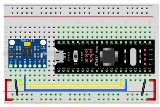
I have the following code for an accelerometer sensor, MPU6050.
#include "stm32f407xx.h"
#define MPU6050_ADDR 0xD0
#define SMPLRT_DIV_REG 0x19
#define ACCEL_CONFIG_REG 0x1C
#define ACCEL_XOUT_H_REG 0x3B
#define PWR_MGMT_1_REG 0x6B
#define WHO_AM_I_REG 0x75
int16_t x_read=0,y_read=0,z_read=0;
float x_accel,y_accel,z_accel;
uint8_t check,temp;
void GPIO_Config(void)
{
    RCC->AHB1ENR |=(1UL<<1);//Enable clock for port B
    GPIOB->MODER |=(2UL<<12);//PB6 to alternate function pin
    GPIOB->MODER |=(2UL<<14);//PB7 to alternate function pin
    GPIOB->PUPDR |=(0x5UL<<12);//set PB6 and 7 as pull up pins
    GPIOB->OTYPER |=(0x3UL<<6);//Set PB6 and 7 as open drain
    GPIOB->OSPEEDR |=(0xAUL<<12);//Set PB6 and 7 as high speed
    GPIOB->AFR[0] |= (0x44<<24);//Set PB6 and 7 to alternate function 4
}
void I2C_Config(void)
{
    RCC->APB1ENR |=(1UL<<21);//Enable I2C clock
    I2C1->CR1 |= (1UL<<15);//Reset I2C
    I2C1->CR1 &= ~(1UL<<15);
    I2C1->CR2 |=(16UL<<0);//Set peripheral clock at 16MHz
    I2C1->OAR1 |=(1UL<<14);//Should be set high
    I2C1->CCR |=(0x50UL<<0);//Set SCL as 100KHz
    I2C1->TRISE |=(17UL<<0);//Configure maximum rise time
    I2C1->CR1 |= (1UL<<0);//Enable I2C
}
void I2C_Start (void)
{
    I2C1->CR1 |= (1<<10);//Enable the ACK Bit
    I2C1->CR1 |= (1<<8);//Send the   start bit
    while (!(I2C1->SR1 & (1<<0)));//Wait for SB bit to set
}
void I2C_Write(uint8_t data)
{
    while (!(I2C1->SR1 & (1<<7)));//Wait till TX buffer is empty
    I2C1->DR = data;//Write data to I2C slave
    while (!(I2C1->SR1 & (1<<2)));//Wait till Byte transfer is completed
}
void I2C_Address (uint8_t Address)
{
    I2C1->DR = Address;  //  send the slave address
    while (!(I2C1->SR1 & (1<<1)));  // wait for ADDR bit to set
    temp = I2C1->SR1 | I2C1->SR2;  // read SR1 and SR2 to clear the ADDR bit
}
void I2C_Read (uint8_t Address, uint8_t *buffer, uint8_t size)
{
    int remaining = size;
    if (size == 1)
    {
        I2C1->DR = Address;  //  send the address
        while (!(I2C1->SR1 & (1<<1)));  // wait for ADDR bit to set
        I2C1->CR1 &= ~(1<<10);  // clear the ACK bit
        temp = I2C1->SR1 | I2C1->SR2;  // read SR1 and SR2 to clear the ADDR bit.... EV6 condition
        while (!(I2C1->SR1 & (1<<6)));  // wait for RxNE to set
        buffer[size-remaining] = I2C1->DR;  // Read the data from the DATA REGISTER
    }
    else
    {
        I2C1->DR = Address;  //  send the address
        while (!(I2C1->SR1 & (1<<1)));  // wait for ADDR bit to set
        temp = I2C1->SR1 | I2C1->SR2;  // read SR1 and SR2 to clear the ADDR bit
        while (remaining>2)
        {
            while (!(I2C1->SR1 & (1<<6)));  // wait for RxNE to set
            buffer[size-remaining] = I2C1->DR;  // copy the data into the buffer
            I2C1->CR1 |= 1<<10;  // Set the ACK bit to Acknowledge the data received
            remaining--;
        }
        while (!(I2C1->SR1 & (1<<6)));  // wait for RxNE to set
        buffer[size-remaining] = I2C1->DR;
        I2C1->CR1 &= ~(1<<10);  // clear the ACK bit
        I2C1->CR1 |= (1<<9);  // Stop I2C
        remaining--;
        while (!(I2C1->SR1 & (1<<6)));  // wait for RxNE to set
        buffer[size-remaining] = I2C1->DR;  // copy the data into the buffer
    }
}
void I2C_Stop (void)
{
    I2C1->CR1 |= (1<<9);  // Stop I2C
}
void configureLED(void)
{
    RCC->AHB1ENR |=(1UL<<3);  //Enable GPIOD clock
    GPIOD->MODER &= ~(0xFFUL<<12*2);
    GPIOD->MODER |= (0x55UL<<12*2);//Set Pins PD12-15 as output
}
void MPU_Write (uint8_t Address, uint8_t Reg, uint8_t Data)
{
    I2C_Start ();
    I2C_Address (Address);
    I2C_Write (Reg);
    I2C_Write (Data);
    I2C_Stop ();
}
void MPU_Read (uint8_t Address, uint8_t Reg, uint8_t *buffer, uint8_t size)
{
    I2C_Start ();
    I2C_Address (Address);
    I2C_Write (Reg);
    I2C_Start ();
    I2C_Read (Address+0x01, buffer, size);//To read, set LSB to 1
    I2C_Stop ();
}
void MPU6050_Init (void)
{
    uint8_t check;
    uint8_t Data;
    MPU_Read (MPU6050_ADDR,WHO_AM_I_REG, &check, 1);//Check device ID
if (check == 104)  // 0x68 will be returned by the sensor
{
    Data = 0;
    MPU_Write (MPU6050_ADDR, PWR_MGMT_1_REG, Data);//Power up the sensor
    Data = 0x07;
    MPU_Write(MPU6050_ADDR, SMPLRT_DIV_REG, Data);//Sampling rate of 1KHz
    Data = 0x00;
    MPU_Write(MPU6050_ADDR, ACCEL_CONFIG_REG, Data);//accelerometer range=+/- 2g
}

}
void MPU6050_Read_Accel (void)
{
    uint8_t Buf[6];
    // Read 6 BYTES of data starting from ACCEL_XOUT_H register
    MPU_Read (MPU6050_ADDR, ACCEL_XOUT_H_REG, Buf, 6);
    x_read = (int16_t)(Buf[0] << 8 | Buf[1]);
    y_read = (int16_t)(Buf[2] << 8 | Buf[3]);
    z_read = (int16_t)(Buf[4] << 8 | Buf[5]);
    x_accel = x_read/16384.0;
    y_accel = y_read/16384.0;
    z_accel = z_read/16384.0;
}
int main ()
{
    configureLED();
    GPIO_Config();
    I2C_Config ();
    MPU6050_Init ();
    while (1)
    {
        MPU6050_Read_Accel ();
    }
}
Initially STM32CubeIDE was able to show live expressions as dynamically changing, basically saying that circuit was working. It happened twice and now it doesn't work anymore, and I am unable to figure out why. A quick pause in debug mode showed me that it is stuck at this line:
while (!(I2C1->SR1 & (1<<1))); // wait for ADDR bit to set
The above line is in I2C_Address function. Is there a problem with the code ? Or connections ?
I made the above connection, except with STM32F4.
Edit: This is what STM32CubeIDE shows:
Edit: I have not included pullup resistors in the schematic, but I have used them. 4.7K for 5V


PB6andPB7pins are 5 V-tolerant I/Os, but internal pull-up and pull-down resistors must be disabled (the code enables pull-ups). However, the MPU6050 datasheet says the absolute maximum input voltage on the SCL and SDA pins is-0.5V to VDD + 0.5V. I.e. pull-ups to 5 V might have damaged the MPU6050. – Chester Gillon Nov 27 '23 at 23:21