0

I've been trying to get the Astable Multivibrator Circuit to work for a long time now, and I think I lack the knowledge to understand what's going on here.

The situation is as follows: I've checked every connection, changed the values of components, checked each component for functionality before soldering, and confirmed correct continuity on every row.

The circuit is drawing 0.086A. At 10V, there is no oscillation on any row. All I'm measuring is a voltage of 1.4V constantly after R1 and R4.

Values of Components:

R1 = 200 Ω
R2 = 1k Ω
R3 = 1k Ω
R4 = 670 Ω
Q1,Q2 = 2N3904
C1,C2 = 22uF

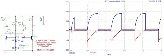
Link to Circuit Simulation.

Images:
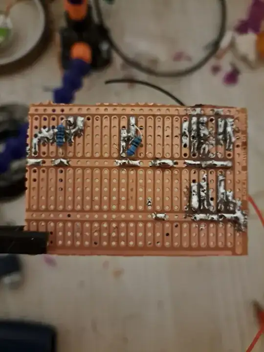
enter image description here

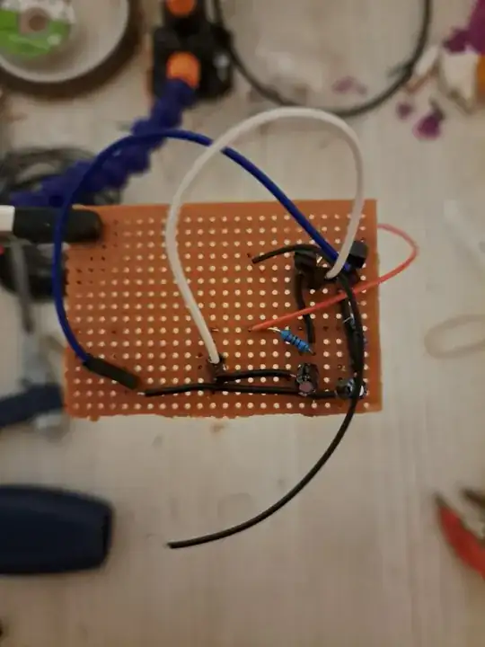
enter image description here

enter image description here

Sorry for the bad soldering, but it became really challenging to keep it clean while constantly swapping out components.

Elektroney
  • 21
  • 2
  • Check that you have the transistors in the right way around. –  Nov 23 '23 at 17:56
  • 1
    Too small resistance in bases put transistors into deep saturation. So the circuit rather latches than oscillates. This become worst in last decades since common bjts in markets have so high beta like >300. – Michal Podmanický Nov 23 '23 at 18:55
  • user350400 its soldered the correct way – Elektroney Nov 23 '23 at 20:31
  • 1
    I would suggest that you develop a working version of the required circuit on breadboard, where you can swap trial components in and out easily, before commiting the final version to a soldered circuit board or PCB. –  Nov 23 '23 at 21:38

2 Answers2

2

Base resistors should be at least 10/20 times collector resistors.
These collector resistors should not be too low -> 1 kOhm.
Then the base resistors should be something like 10 kOhm or 20 kOhm.
NB: the base-emitter space is not always simulated correctly!

Sometimes, the "circuit" is "stuck" in one state. One must then modify some component.
This happens commonly when using polarized capacitors of "high" values.
Must be clear with the "paralleled" resistor on every polarized capacitor ...

enter image description here

Antonio51
  • 13,128
  • 1
  • 7
  • 22
  • This did not solve my Problem sadly but theres something that changed im getting 6.8v on the base of T1 And getting 10v on both sides of C1, I changed R2 and R3 to 20k Ω – Elektroney Nov 23 '23 at 20:16
  • Have you changed also other resistors R1 -> 1 kOhm? There is a problem with 6.8V on base of T1 ? – Antonio51 Nov 23 '23 at 21:17
  • I replaced r1 and r4 with 500 Ohm cause i accidently cut them off but i didnt have matching values left in my drawer, didnt think it was worth noting, i mean 6.8v on T1 is a problem cause its supposed to be oscillating – Elektroney Nov 23 '23 at 21:22
0

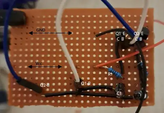
The base connections aren't crossed. You need to swap one end of the white and blue wires.

enter image description here

As Antonio said, the base resistors should be much larger than the collector resistor. I would use 22k and 1k. Put an LED in series with the collector resistor so you can see the circuit in action.

It is normal for the base voltage to go negative in this circuit. But, if Vcc is more than about 9 volts, it may go negative enough to stress the Vbe junction (typically -6 V). You can remove this risk by adding a diode in series with the base.

FYI: here is how I would have built this. How should I wire my circuit onto a perfboard?

Mattman944
  • 15,935
  • 1
  • 20
  • 47