Update: As Peter Bennett pointed out, if the LEDs are rated for 12 V the whole resistor thing becomes moot. If you were to be using standard LEDs the following would apply.
If you are using two of the same value resistor you could change it to use one resistor before the switch like this:
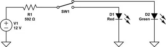
simulate this circuit – Schematic created using CircuitLab
Or you could put the resistor between the LEDs and ground like this:
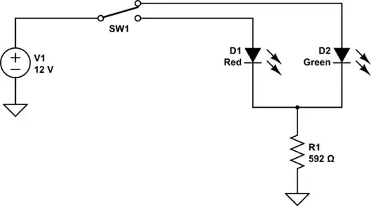
simulate this circuit
This would save you a resistor. The drawback is that you have two different color LEDs and they will have different voltage drops so the currents through them will be different which may affect their relative brightness. With a separate resistor for each LED you can use different values for each to set the LED currents independently. In most cases you'll just want the LEDs to light up bright enough to see them and to also limit the current to keep them from burning out, so the single resistor will work fine in many cases.
So let's see what the difference in current will be.
According to some online resources at 20 mA a red LED might have an \$V_F\$ of 1.6 V to 2.0 V while a green LED would be 1.9 V to 4.0 V, so we'll take the worst case scenario.
For the red LED:
$$
I_{red LED} = \frac{12.0 V-1.6 V}{592\Omega} = 17.6 mA
$$
For the green LED:
$$
I_{green LED} = \frac{12.0 V-4.0 V}{592\Omega} = 13.5 mA
$$
Not a huge difference even at the extremes, but you'd have to try it with the actual LEDs to see if there is enough difference in brightness to justify using separate resistors for each LED.
