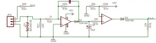
I am having a difficult time understanding a few things in regards to the ground fault detection circuit below. I have found this circuit while investigating ground fault detection. I intend to build my own circuit for use in my system and am using this as a starting point.
Note the circuit below is to be matched with this CT.
Now, my questions are...
- I assume the intent of D1 is to provide over voltage protection. However, I don't see how that works with this particular diode. These are standard Shottky diodes which don't conduct when reversed biased. Why not just use a TVS for this sort of thing? I must be missing something here. I feel silly asking...
- R17 becomes the burden of the CT and develops a voltage proportional to the current. This particular circuit uses a value of 330 ohms. If I understand the CT datasheet correctly that yields a voltage around 6.5V at the rated current which doesn't seem like a good choice. However, I am not sure I read the datasheet correctly. Is Te turns ratio? How do I chose the value R for a GFI situation? The data sheet recommends choosing R such that V < .8 Vl but they fail to specify what Vl is (or perhaps I should know this).
- The threshold for tripping is set by R15 and R14. C14 would add some delay. R16 and R20 act to amplify the current reading. How would appropriate values be determined here? In other words, what's safe or customary?
Note that this is a one off design which wouldn't necessarily have to conform to any regulations but I'd still like to get a handle on this.
EDIT:
The AC leads (hot, hot, ground) will enter the enclosure and run to relay contacts. The leads then run from the relay contacts and exit the enclosure. I was planning only to run the two hot legs through the CT right where they enter the enclosure.